Turn on the receiver, talk in the microphone and the sound goes from here to there … magic, right?
Putting the dark arts aside for a moment, understanding (and measuring!) what the signal actually endures in getting from mic to receiver can come in very handy when and if RF problems arise.
In general terms, your receivers need to see a signal from your wireless mic that is 20 dB or more above your noise floor. Within a reasonable range, more signal to noise is better of course and will lead to less nail-biting over dropouts.
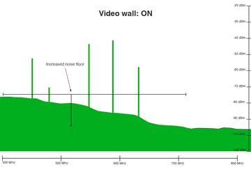
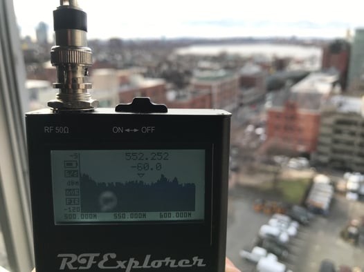 High noise floor conditions like this -60 dB level in a downtown high rise hotel can present a nightmare for wireless mic operation
It all starts with the power output from your wireless mic transmitter. More is better, right? Well yes and no. More power increases intermod problems when using more than a single transmitter and a big problem when using a dozen or more. And more RF flying around the room will sooner or later end up in your system as noise.
To better understand this we’ll need to calculate the signal’s path in dB, also referred to a as a link budget.
So here’s what typical levels look like starting at the mic transmitter:
50mW = +17 dBm
30mW = +15 dBm
10mW = 10 dBm
Generally speaking we will need to subtract a little for Transmitter mis-match loss
Transmit antenna loss = -3dB
Maybe you never thought about this but transmitters in the hands of humans (or on their belts) suffer a fair amount of loss. It will also greatly reduce the signal if the talent covers the transmit antenna with their hands. It should be noted that when working with really large people this number can easily double.
Handheld loss = -8 dB
Beltpack loss = -20 dB (double if in your back pocket)
Free space path loss happens as your signal travels through the air. This is why we urge users to keep mics close to receiving antennas. The loss factor changes with frequency so we’ll consider the center of the UHF TV band at 550 MHz.
loss @ 100’ = -57 dB
loss @ 50’ = -51 dB
loss @ 25’ = -45 dB
As receive side antennas become more directional they exhibit greater gain. But regardless of gain, you do need to select the proper antenna to achieve the coverage pattern you need.
Whips = + 1.5 dB
LPDAs = + 6 dB
Helicals = +9 dB
Another important factor to remember is the loss as the signal travels through your coax cables. This is called transmission line loss and becomes increasingly important as cable length increases. I’ll give a few examples here, but you should refer to the specs for the coax cable you are using and you should be using the best you can afford.
RG58 loss -12dB/100’
RG8x loss -8dB/100’
LMR400 -4dB/100’
There is a little loss in every BNC connection, some more than others. There is loss if your coax is a bit used and a number of other variables that come into play including cross linear polarization fading. So we’ll throw in a little here
Misc losses in your system. -3dB
So let’s add it up!
30 mW Transmitter +15 dBm
Transmit loss -3 dB
Human absorption -20 dB
Free space path loss 50’ -51 dB
LPDA antenna gain +6 dB
Coax loss 50’ RG8x -4 dB
Other misc -3 dB
.........................................................................
Total RF energy at receiver antenna port = -60 dBm
So assuming your mic is assigned to a clear frequency and your antennas are properly aimed and not suffering from polarity losses, we’re looking pretty good in this example as long as our noise floor remains below -80 dB. Your mileage may very well vary!
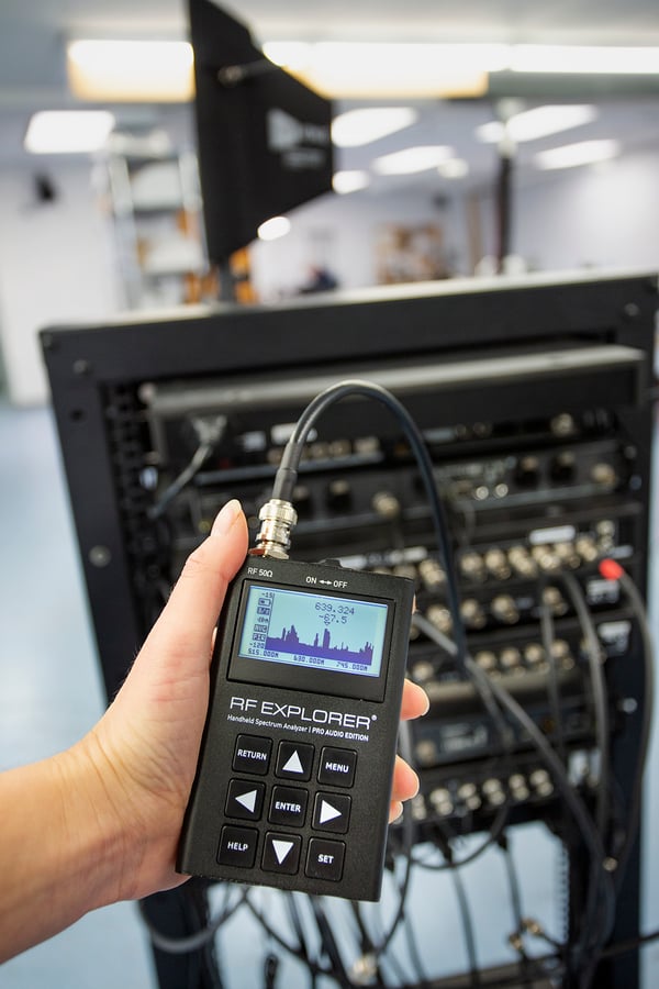
On the other hand, you can avoid counting on your fingers and toes by simply measuring your signals with a spectrum analyzer such as our new RF Explorer Pro Audio Edition. You will get an exact answer and not just a theoretical figure as well as being able to finally see any signal level issues you might be up against. Best practice for this is patching right into your antenna distro on a spare output to you can see exactly what your receivers will see. This includes all the loss through the signal path as well as any noise introduced in the amplifiers in the antenna distribution system. If your signals appear to be low, step through the rest of the signal path back to the receive antennas to check coax cable performance, antenna positioning, and any other gear in-line to optimize for best signal to noise.
Got any other tips on managing link budgets? Be sure to leave them in the comments below or Contact Us here for assistance.