Never heard of antenna distribution for wireless audio? Or heard about it, but don't really know what it is?
Through countless conversations with our customers, I've discovered that many troublesome "interference" cases boil down to users operating multiple channels without any antenna distribution, or existing distribution that is improperly deployed.
With a surprisingly large number of these conversations, adding proper distribution completely eliminates dropouts and interference.
What is Antenna Distribution?
Antenna distribution refers to numerous methods of distributing RF signals through one or many antennas.
I wrote a more detailed post on the definition of antenna distribution several years ago, when I was learning the definition myself.
For those unconcerned with lengthy definitions, antenna distribution is about two things:
- Improves system performance and reliability
- Reduces clutter and chaos in the rack or FOH
Core distribution equipment includes:
- External antennas
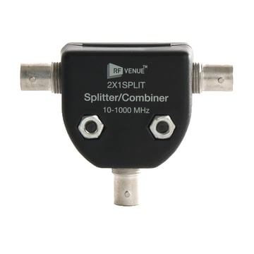
- Mic distributors (distro) or IEM/IFB combiners (transmitter combiner)
- Coaxial cabling
- Power supplies and cabling
- (less frequently) RF to fiber-optic converters, or RFoF--fiber replaces coax
(Terminology around combiners vs distributors is confusing. Clear it up here)
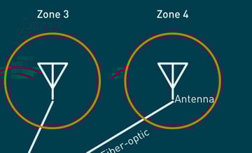
Antenna distribution, when you get up to the big leagues, is also about engineering distributed antenna systems (DAS), also known as multi-zone distribution. A multi-zone system allows talent to wander through coverage “zones” or rooms without losing reception.
For the average professional, multi-zone's aren't usually necessary, though we sometimes get asked how to set up a simple, two-zone DAS. The answer is here.
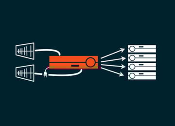
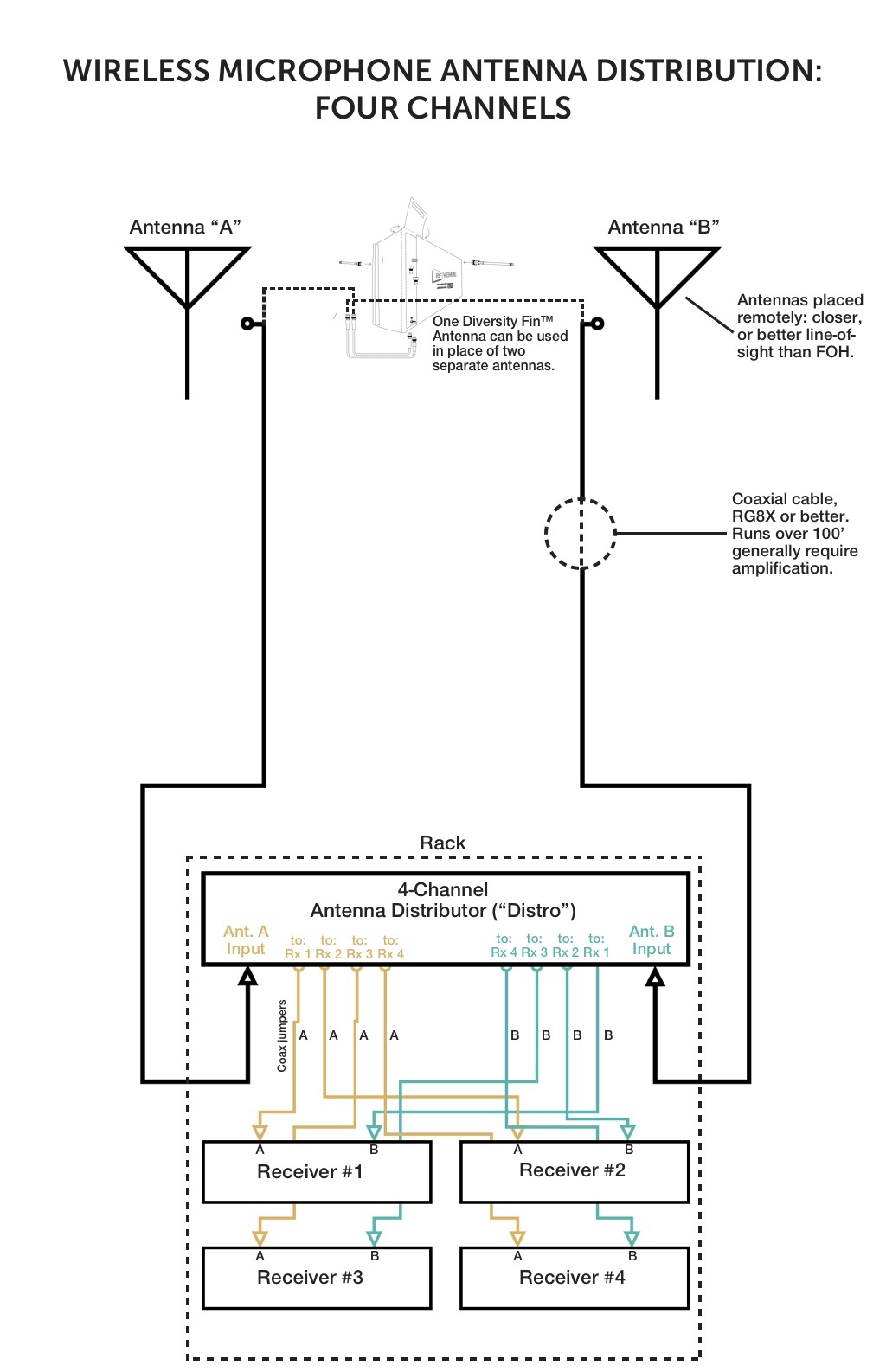
Antenna Distribution for Wireless Microphones
You'll need an antenna distributor (distro), coaxial cable, and two external antennas.
Then Plug N' Play, as follows:
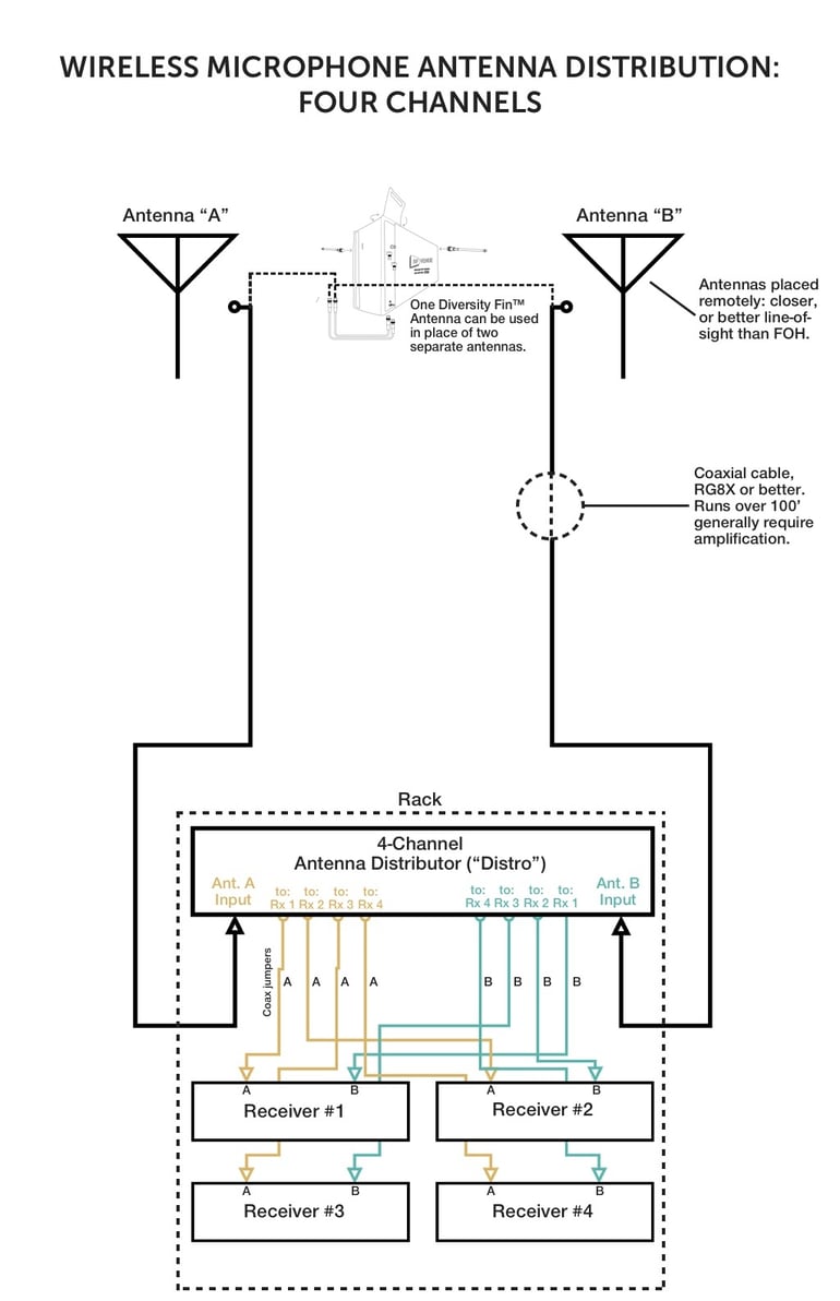
download this diagram
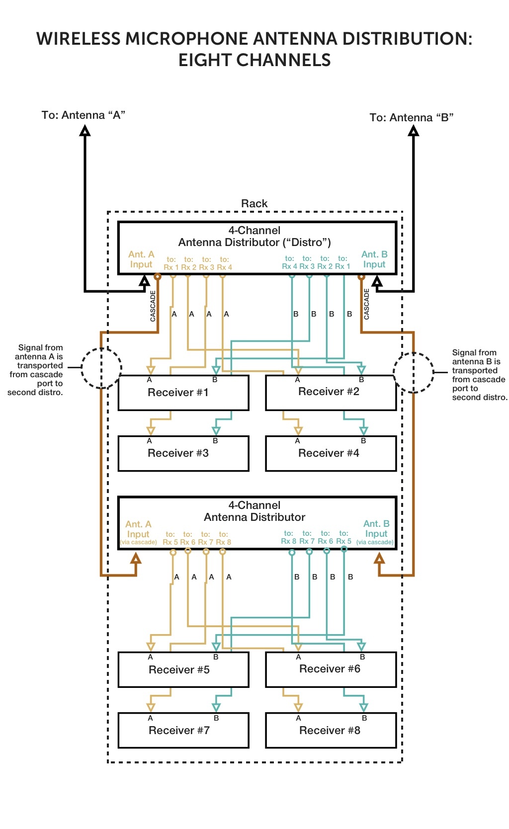
More than four channels? No problem. If your antenna distributor has a cascade port, you can cascade up to 16 receivers together using four distros. For distros without dedicated cascade ports, you can also cascade via the "daisy-chain" method by sacrificing one of the four A and B antenna outputs to use as a cascade port--which means if you want to distribute 8 receivers, you'll need three distros instead of two.
Here's a diagram for an 8 receiver setup.

download this diagram
Some professionals like to position each successive distro beneath the previous receivers in the previous cascade, and above the receivers that distro will distribute to, as shown above. Others like to keep all of the antenna distributors at the top, with 8, 12, 16 or however many receivers are in the system below the bank of distros. This is often a matter of personal preference.
Antenna Distribution for IEMs, and IFBs
Antenna distribution is also used for devices that transmit, rather than receive. Like in-ear monitors and IFBs.
Antenna distribution is especially important for transmit devices mounted in a rack, because using co-mingled whip/dipole antennas at the rack risks causing severe interference between the transmitters, because the antennas are so close to one-another.
Benefits of antenna distribution for IEM transmitters include:
- N number of transmitters: one antenna. Clean, easy. No crazy antenna farms.
- Freedom to place that one antenna elsewhere in venue or on stage wings for better line-of-sight and improved SNR.
- Ability to use specialized antennas designed specifically for IEM applications, like the CP Beam.
- DC power distribution on most Tx distributors means no wall warts and a cleaner looking rack
- Racks without PSUs and multiple whip antennas also provide better RF performance. This is especially true with IEMs, vs. passive wireless microphone antenna distribution.
IEMs with diversity transmitters and diversity belt-pack receivers exist, but are rare, and on the high-end of the market. It's best to consult your manufacturer if you plan on using antenna distribution for diversity transmitters.
Anyways, here we go:
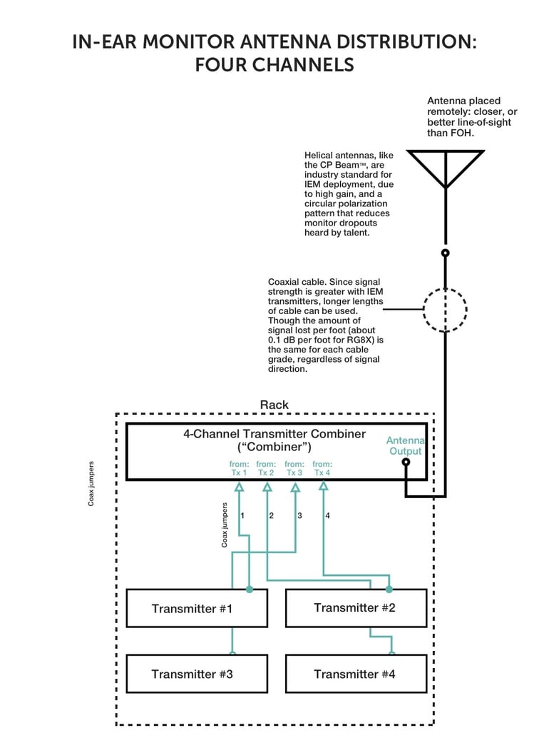
download this diagram
IEM transmitter combiners can be used together for more than four channels, but they cannot be daisy chained. Follow the instructions at this link to learn how to create an eight channel combiner out of two four channels without setting something on fire.
NOTE: There is something missing from these diagrams--power cables. We deliberately omitted PSU/power cabling to make the signal distribution easier to understand. However, your IEM or wireless mic rack unit has a power plug and cord, and that cord is located in the same area as the coaxial cable jumpers. If you have a distributor or combiner with an integrated PSU that supplies power to the rack units, like the DISTRO4 and COMBINE4, all you need to do is connect DC jumpers between the power inputs on the receivers or transmitters and plug the jumper into the DC jacks on the distribution unit. Otherwise, you'll just plug the receivers into a power-strip using wall-warts.
