New England-based integrator Commlink showcases a well-engineered multi-zone wireless microphone system at the newly renovated Cathedral of the Holy Cross in Boston
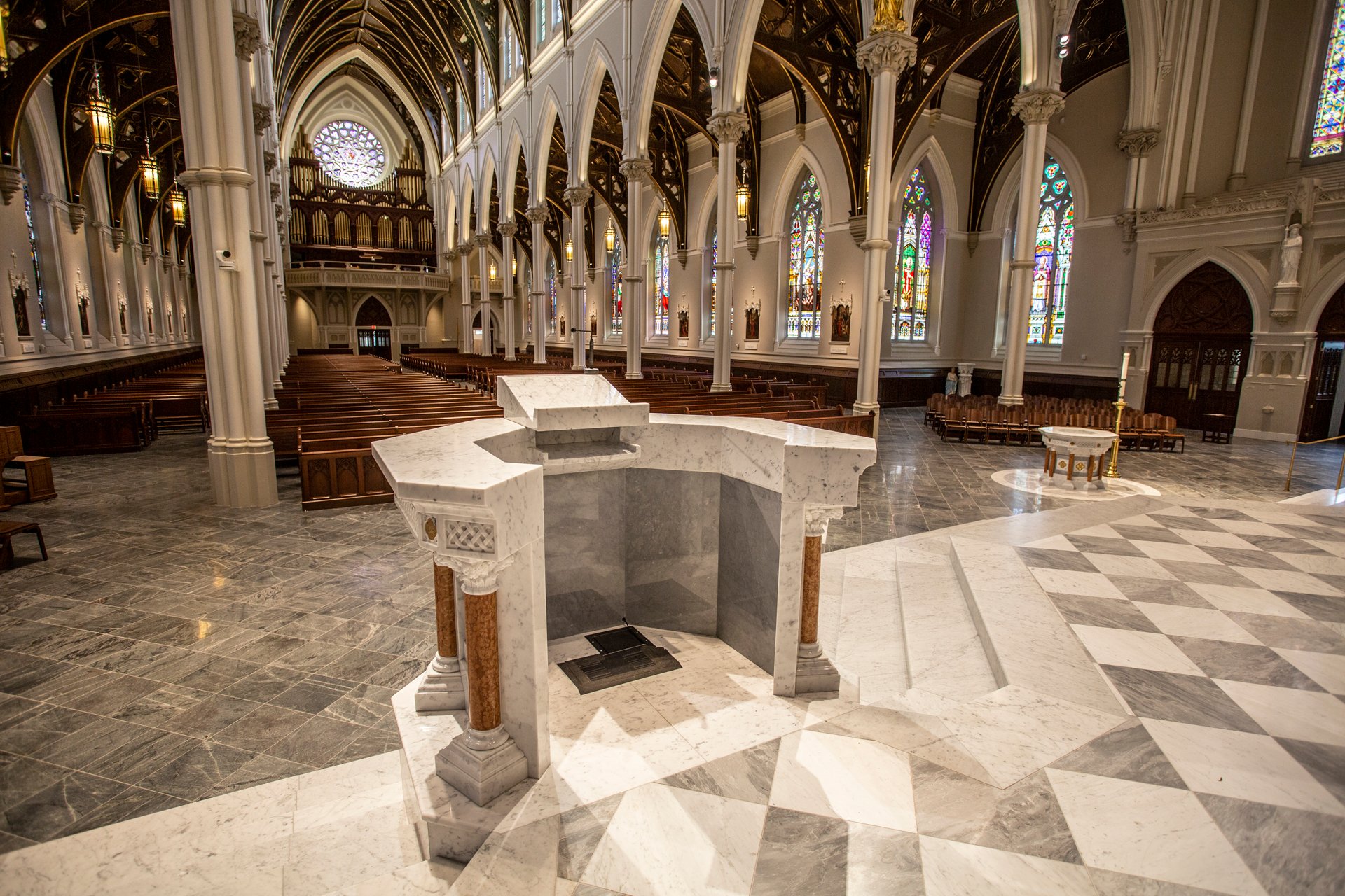
This spring, the Archdiocese of Boston unveiled a $26M restoration of the 150 year old Cathedral of the Holy Cross. An architectural marvel, the 2000 seat cathedral is the largest in New England, and surpasses St. Patrick's in New York City in size. This poses a challenge in configuring a "works everywhere" wireless mic system. Landry Audio, a division of CommLink Integration, took on the project.
Multi-zone wireless microphone projects, sometimes referred to as DAS (short for Distributed Antenna System) are unique in the world of wireless audio. Often times these projects don't have a very high channel count, since a musical act with 8 wireless microphones and 8 channels of IEMs typically perform in one fixed stage area. (There are exceptions of course, like if you're Metallica 🤘)
Spectrum analysis, antenna placement, and real world stress testing the system are the keys to success in multi-zone wireless audio
And this was the case in the cathedral project, where Commlink only needed eight channels of wireless microphones. Easy, right?
Not exactly.
Those eight mics need to work reliably across a massive floor plan, well out of range and line of sight for any single set of receive antennas. And naturally the 150 year old architecture and strict aesthetic limitations added even more to the challenge.
Wireless Mic System and Rack Wiring
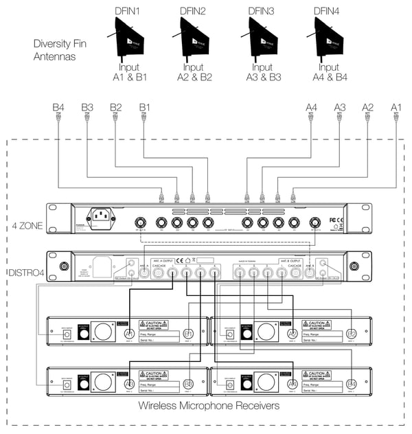
An example wiring configuration for a 4 Zone system, including antenna distribution and four wireless microphone receivers
While determining coverage areas and antenna type may require a bit of trial and error, the actual wiring for a multi-zone system at the rack-end is pretty straight forward. The 4 Zone serves as the "head end" of the system, combining each A and B diversity channel down to a single A and a single B. This output pair then connects to a DISTRO4 or other multi-channel antenna distribution system, which then feeds the inputs on the wireless mic receivers.
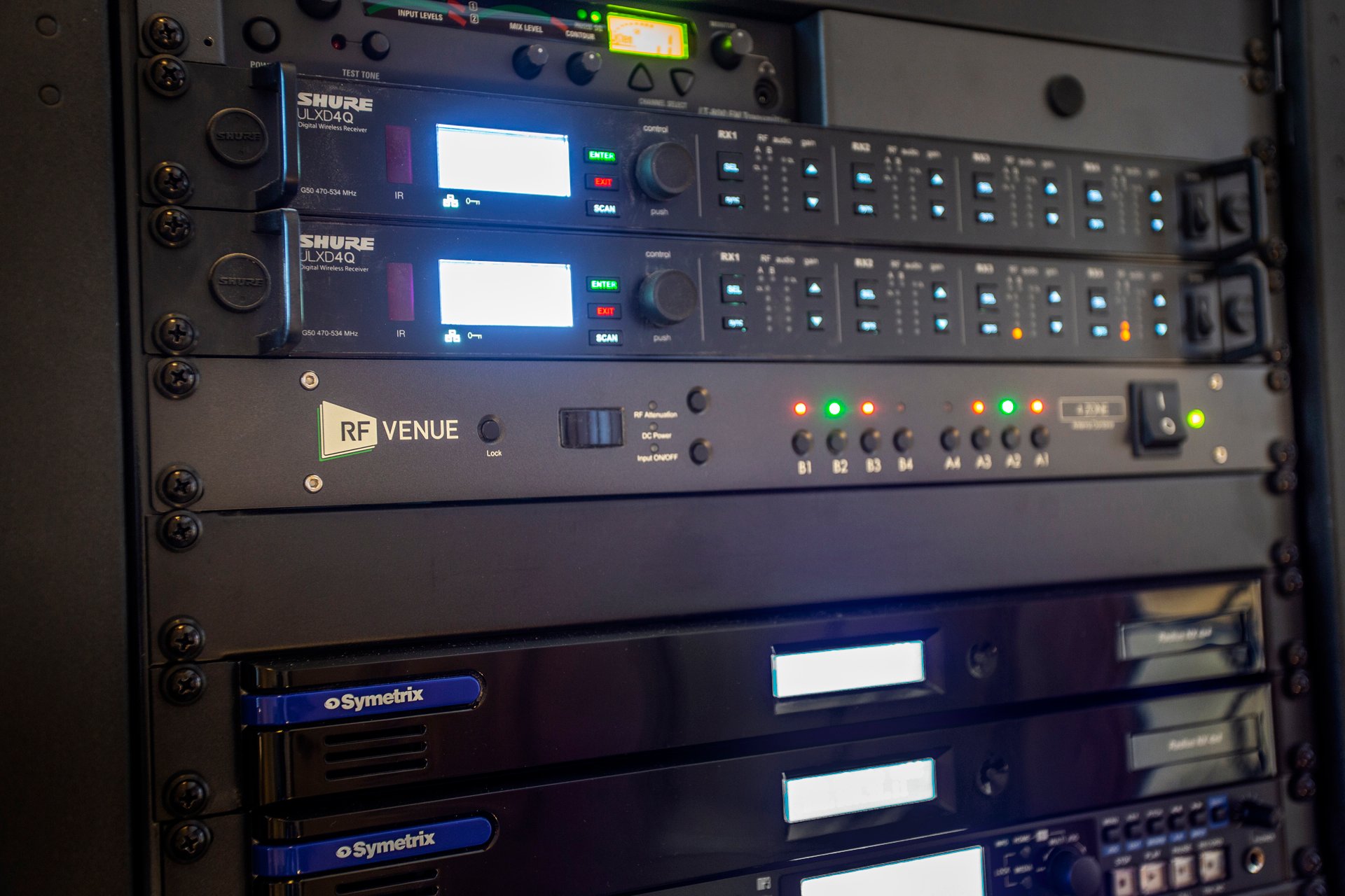
At the rack, Commlink configured this multi-zone system using 2 cascaded Shure ULXD4Q wireless mic receivers and an RF Venue 4-Zone.
Based on the location of the AV rack (inside a closed office area) - an estimation was then made over practical multi-zone coverage for the wireless system, taking into account antenna type, placement, and optimal line of sight conditions that would meet the strict aesthetic requirements of the project. Coaxial cable run length vs. RF over fiber distribution was also considered.
Antenna Selection and Placement
Three zone coverage area layout, from left to right, Zones 3-2-1
A pair of low profile Shure UA864 antennas were mounted on the wall of the altar area, out of sight from the congregation, this section of the cathedral comprised Zone 1, and had an effective range just to the edge of the altar, which is where Zone 2 picks up coverage.
Zone 2 begins in the transcept area and utilizes the installation white Diversity Fin Antenna. From a single point of installation high up on the wall of the cathedral and cleverly camouflaged, the polarization diversity antenna system is nearly impossible to find, even if you're looking for it. Over larger areas, particularly indoors with a variety of reflective surfaces, like the marble floor of the cathedral, signal fades due to angle and orientation of the signal are even more pronounced. This is where the Diversity Fin excels in maintaining adequate signal level due to cross linear polarization fading (more info and a free eBook available here).
Diversity Fin Antenna in Zone 3, high up on a column with line of sight to the large congregation area
The largest area in the cathedral, the main congregation, is where Zone 3 picks up the roving mic transmitters. Here another Diversity Fin in white was installed high up on a column. For certain church services, the microphone transmitters will move down the long walls of the cathedral, and the system would need to reach areas well out of reach of the first two zones. There was a chance this area may require a 4th Zone, so Commlink budgeted a backup plan to further extend the system with another Diversity Fin antenna if needed, which would then likely require an RF over Fiber solution like Optix due to the 2000 ft potential cable run to the rear of the cathedral. Having thoroughly tested the three zone coverage areas after installation, the 3 Zone configuration was deemed adequate. The Zone 3 Diversity Fin also employed in-line amplifers to boost the signal and makeup the signal loss over a run of several hundred feet of RF Venue RG-8X cable. These in-line amplifiers are powered by DC on the coaxial lines provided by the 4 Zone.
Testing Zone Coverage
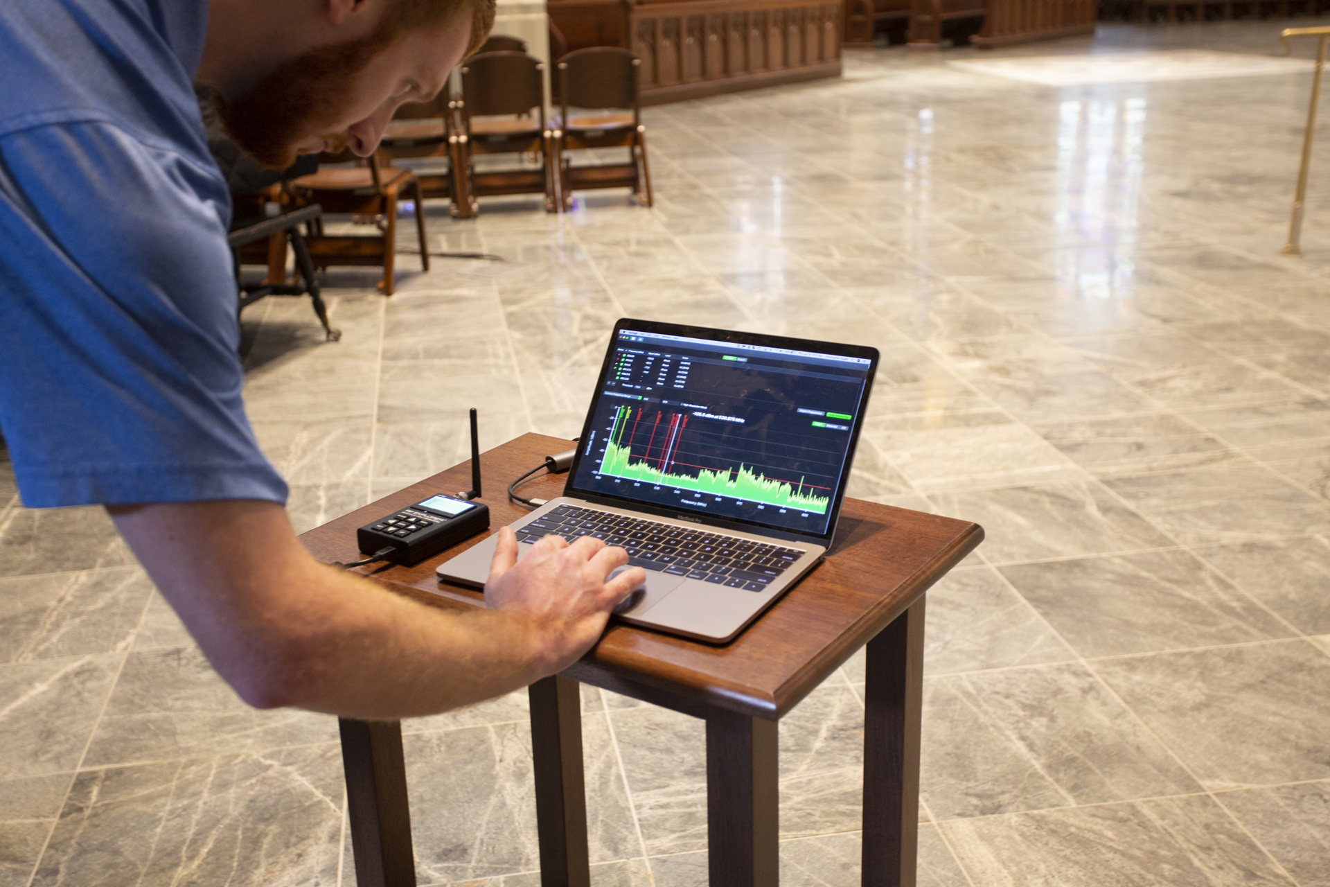
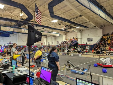
Walk testing transmitters while monitoring RF signal levels the RF Explorer Pro Audio spectrum analyzer. Shown here are the furthest ranges of this zone where the signal to noise is low and then drops off to red once out of range.
Tapping into each zone with a spectrum analyzer, while walk testing the transmitters set to various power levels (low to high) is an effective way to measure coverage. (If you missed our previous series on the basics of spectrum analysis for wireless mics, be sure to check that out here). This particular setup seems to work with with the ULX-Ds set to 10 mW, but may benefit to moving up to 20 mw given the large size of the facility. Luckily the spectrum conditions at the site provide for a low noise floor, and lower transmit power levels work (and save battery life!).
Commissioning
The final handoff of the system was completed, along with documentation for the frequency settings, backup frequencies and other system details.
If you have any other tips for multi-zone wireless systems be sure to add a comment below, and for more information or assistance with a project feel free to connect with us anytime on our Contact Us page.
[Special thanks to Evan Landry at Commlink for the assistance in reviewing and documenting this project and to Jen from the RF Venue team for the amazing photos 👋]