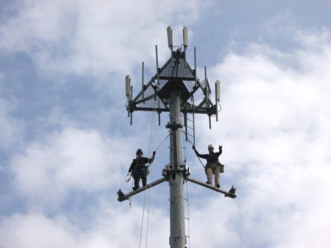
Take a good look at this photograph. What do you see? Besides the telecom employee flashing sign of the horns for some reason from hundreds of feet in the air, you see what you see every day on your drive or commute to and from work - a boring cell tower with its familiar triangular lattice of directional antennas. But have you ever wondered why the antennas are arranged this way? A recent conversation with a wireless industry expert (whose thoughts will be divulged in a future post) led me to look for the answer, and, more challenging still, how it can be applied to wireless audio.
Antennas atop cellular towers are sometimes arranged triangularly to execute an infrastructure that supports a technique called frequency reuse.
As we know all too well, electromagnetic spectrum is finite. The cellular industry has devised clever ways to allow a greater number of devices to cohabitate the same area. Frequency reuse refers to both infrastructure and network technologies that allow radio devices to communicate on the same frequencies in adjacent or nearly adjacent spaces, which allows for a greater density of devices per given area.
Here’s an analogy from the single-transmit model from the broadcasting world.
Imagine one television station broadcasting on one frequency at extremely high power, like this.
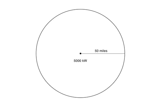
The dot in the center is an antenna radiating equally in all directions. The circumference of the circle represents the lowest signal at which a TV receiver would be able to pick up the signal. This imaginary TV station has a perfectly circular coverage area with a radius of fifty miles. Within this circle, all TVs tuned to this channel’s frequency get good reception. All of these receivers also only have one choice of programming for that particular channel.
That one TV station has a monopoly on that frequency within its coverage area. From a macro perspective, this is not necessarily the most efficient use of spectrum.
If the transmission power of that TV station is reduced, a smaller number of TV receivers will be able to pick up the station. However, other TV stations that fall outside the new coverage area can now use the frequency which was previously occupied.
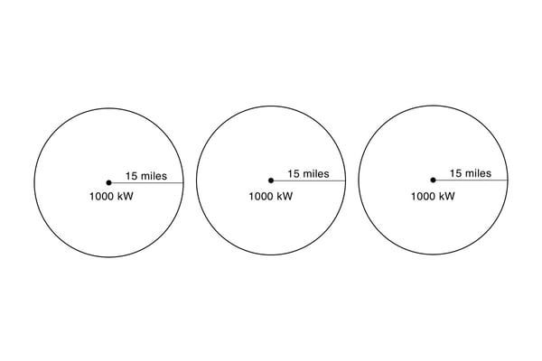
Now, the same area is supporting three different services in the same area as used to fit only one, although receivers are still limited to a choosing only one piece of content (whichever TV station coverage area they happen to sit inside).
This may sound not that magic at first, but consider a scenario where there are two cities five miles apart from one another, where only one frequency is available (for whatever reason), and everyone in each city is living very, very close to one another. Each city wants its own television station that produces programming that caters to the tastes of each unique population.
If the transmission power of either station is such that they have a coverage area with a radius of five or more miles, then the spectrum available to both cities can only support one station, or two stations that interfere with one another.
But if the transmission power is reduced so that the coverage areas are five miles or less, each city gets its very own TV station, interference free, even though both stations are operating on the same frequency.
At this point you are probably saying, “duh.” But this simple concept, that radio waves diminish in strength with distance, which in turn allows for the same frequency to be “reused” by another transmitter at a certain distance away from the previous transmitter, is the seed for some extraordinarily complex geometry that makes modern high density cell and data networks possible.
So, back to the triangle. Why are many cell towers outfitted with a triangular array?
It is my understanding that each cell tower with this triangular structure is situated at the intersection of a carefully engineered hexagonal grid that enables maximum utilization of spectrum.
Here is a representation of this antenna in an overhead view, where the entire tower is transmitting in all directions on only one frequency. I've compared it with the original photograph at the top of this post for clarity's sake.
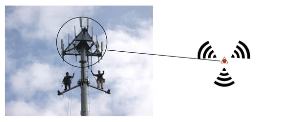
Now imagine there are three different cell phone users within the coverage area of this one tower. Each of the phones wants to communicate with the tower on the same frequency for different purposes. They are unable to do so because only one handset can use the downlink’s frequency at a given time.
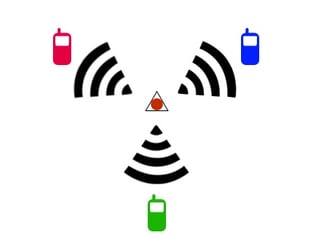
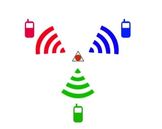
But if each of the cell phone users agrees to use a different frequency, and each of the facets of the triangle uses directional antennas that send different frequencies in different directions, all three of the cell phones can call different people at the same time using different frequencies, like this (each color represents a different frequency):
But that still doesn’t explain why the towers are triangular, instead of some other shape, and how different cell users can use the same frequency.
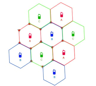
Check this out. Super smart network and RF engineers discovered that if you divide up physical space into hexagonal units, or “cells,” you can maximize spectral efficiency by allowing users who are relatively close to one another use the same frequency, while allowing mobile devices to hand off their frequencies seamlessly as they trasverse one cell to another. Our wireless digital lives are lived inside this honeycomb of hexagonal cells. The illustration below shows how the antenna we've been talking about is situated at the center of three cells, transmitting three different frequencies into those three cells.
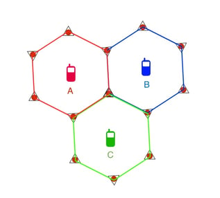
One cell uses one frequency or one carefully planned set of frequencies. Creating coverage in one hexagonal cell is done by placing towers with triangular directional arrays at the intersections of three cells. One inward facing facet of each triangular tower is equipped with a directional antenna that transmits inward on that cell's designated frequency. In this way, cell frequencies can be reused very close to one another, depending on the technology in use.
Now you understand why many cellular base stations are topped with these signature triangular structures.
If you’re still with me, you’re asking, OK, what the hell does this have to do with wireless audio?
It is possible to use a simple model of frequency reuse for certain wireless audio application that allows a much, much higher number of microphones to operate in the same space than would otherwise be possible.
The best applications are where large numbers of microphones are evenly-ish distributed in the same space. The space is small enough so that the typical coverage areas of those microphones overlap, but large enough to allow the partitioning of that space into rudimentary reusable cells.
Typical stage or podium based wireless audio applications are poorly suited to frequency reuse for a few reasons. Mostly because the transmitters and receivers are grouped in clusters distributed irregularly in space. That is, there are 20 transmitters on the stage quite literally within a few feet of one another, and 10 in the booth. There are 20 receivers in the booth, and 10 IEM transmitters there too, while 40 intercom headsets and basestations lurk stage left, right, up down, inside out and underground.
But in a case like a tradeshow, there may be hundreds of microphones evenly distributed inside a 40,000 square foot facility.
Using wireless microphones at tradeshows is notoriously difficult not because it is impossible, but because there aren’t enough frequencies to go around if every user has his/her microphone set to its maximum power and is using amplification or a directional antenna to boost their signal.
That is the first and gut reaction from many engineers and users. Getting interference? Let’s boost the power to get ahead of everyone around us. Of course, everyone else inside the facility has the exact same idea - I need more power, Scotty! - which makes everything worse for everyone, and Hardin rolls in his grave. You get something that looks like this:
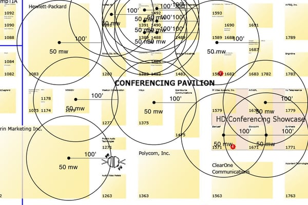 No bueno. Interference City, USA.
What should happen is that everyone turns down their transmitter power to the lowest possible setting. That way, coverage areas don’t overlap, and adjacent or every other adjacent booth is able to use the same frequency without interference. Then, you get something that looks like this:
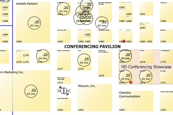
Of course the principles of cellular reuse are somewhat reversed in this scheme. The transmitters are one-way and are moving and the receivers are stationary. And the "basestations" receivers are located willy nilly, while the transmitters are at the center of each "cell," not on the boundary.
I don't think it is inconceivable that a convention center might invest in a project that creates a grid of wireless audio frequency reuse cells across their floor, perhaps with the help of a network engineer. They would have to enforce rules to make sure each mic user either obeys power and location requirements, or uses house equipment outfitted with a reuse protocol, exclusively.
You can also use our RF Spotlight antenna to create frequency reuse cells without necessarily turning down transmitter power, although it works best if you do.
Stadium events also benefit from frequency reuse coordination, and distributed remote antenna systems installed in museums and other large public facilities execute reuse quite well.