[If you missed the beginning of our series on spectrum analysis be sure to check that out here.]
Interference hunting

While you are in the system setup phase, hunting for interference so that it can be avoided is the main reason for employing a spectrum analyzer. In this post we'll take a look at some of the most common examples of interference. Be aware that your scans will likely contain a number of these elements at the same time. We show them isolated here with a broad scan range so you can better visualize their distinct signatures. Should you need to pinpoint one, just adjust the scan range to something narrower as appropriate.
Noise Floor
Your first baseline scan is giving you a good look at your local noise floor.
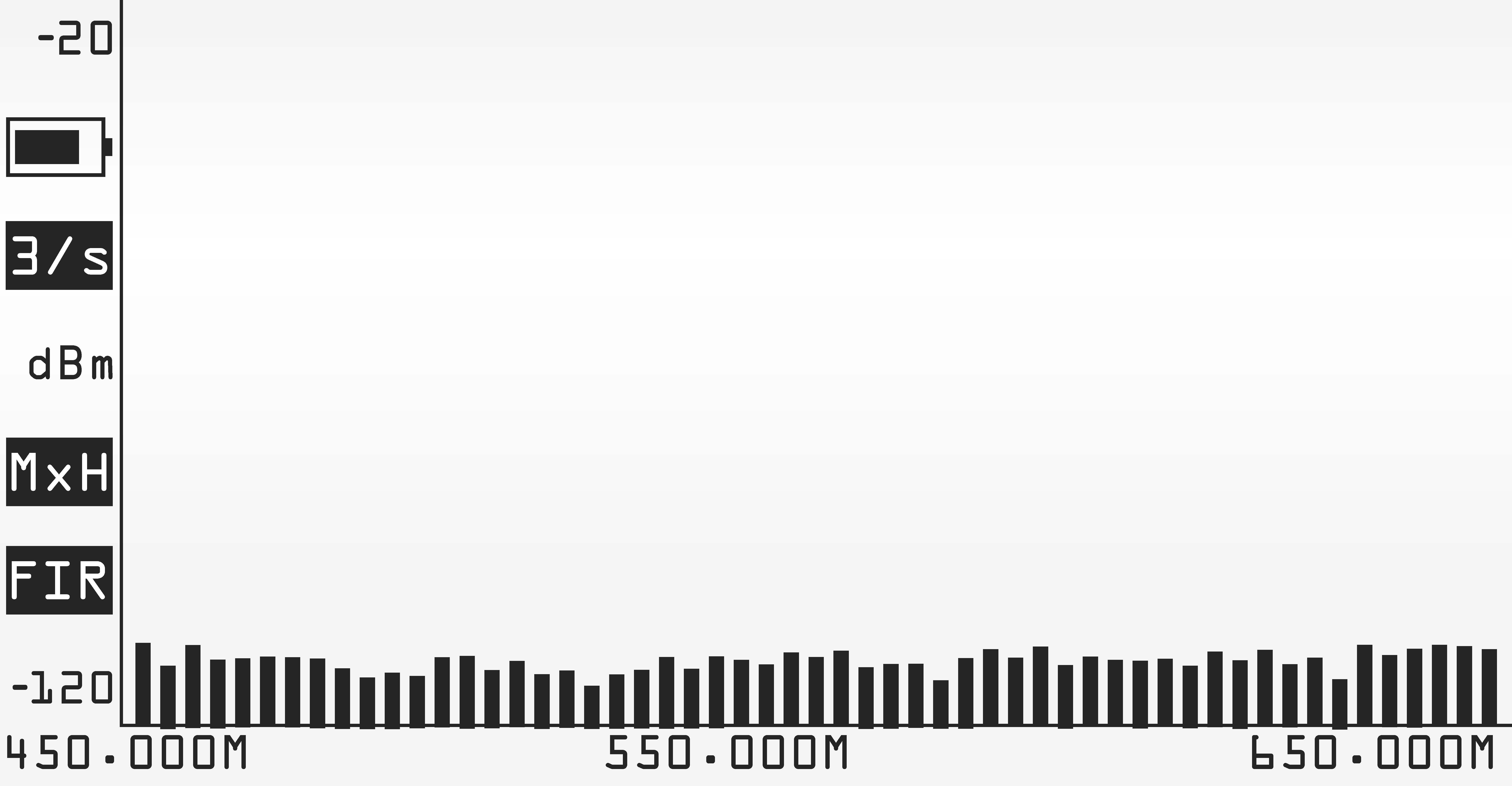
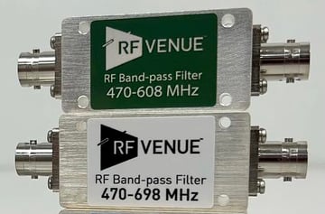
Hopefully the noise floor is shown below (or well below) -80 dB. The lower the better. Reducing the noise floor at the source can be difficult but if your operating environment has a high noise floor, adding Bandpass Filters will usually drop the noise floor by 6-15 dB. Systems can be operated with a high noise floor but they are likely to be more problematic and less reliable. As always, system reliability is directly related to how strong your intended signal is to the noise floor. A good number to shoot for is 20 dB or better, we have more info on optimizing signal to noise by relocating receivers and antennas in this post from the archives.
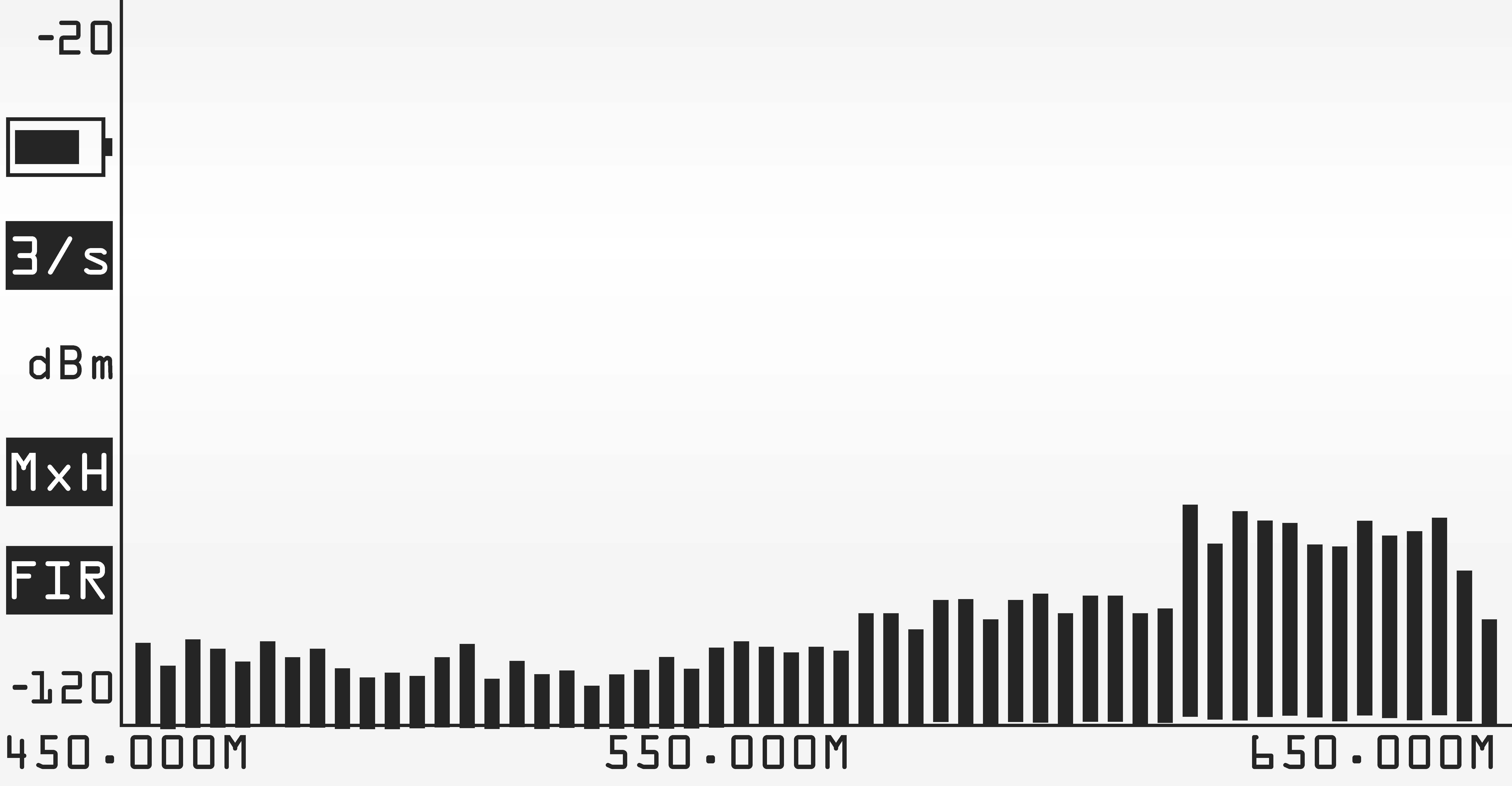
Out of Band Interference
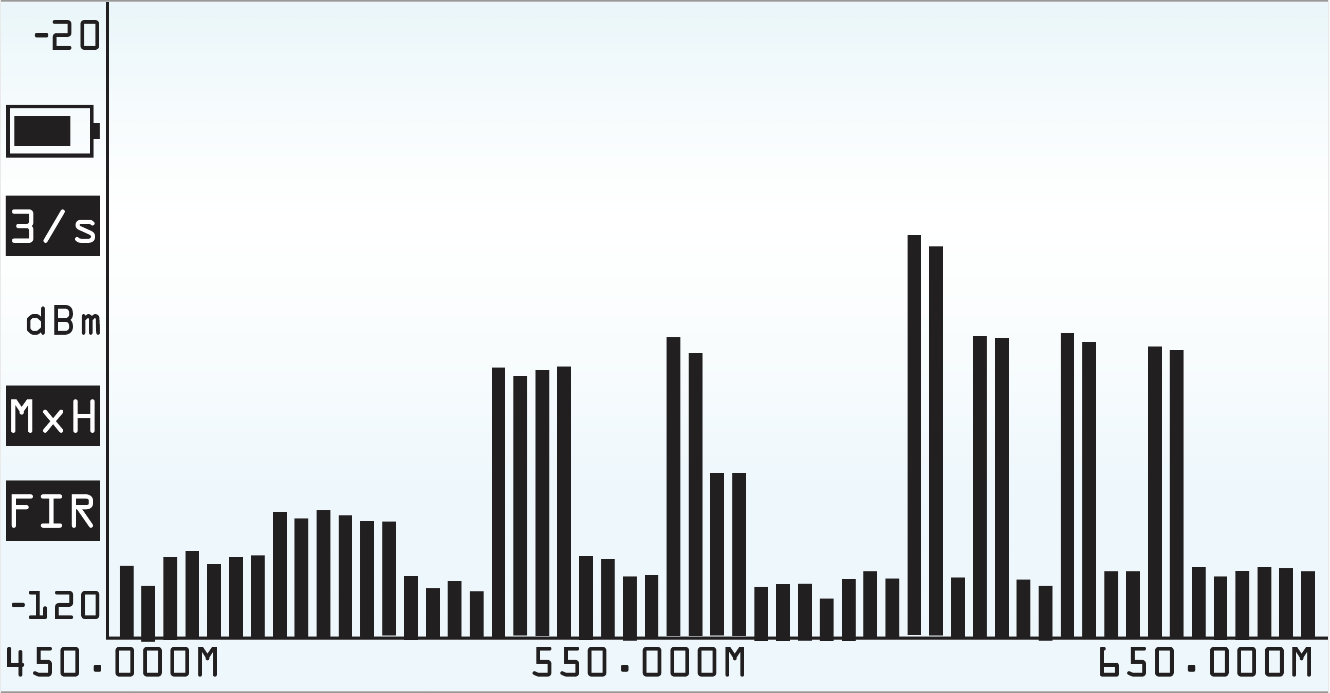
Out of band interference can also contribute to an elevated noise floor. New cellular services such as T-Mobile’s 600MHz service, while operating at 617MHz and above, can readily contribute to higher noise down to the mid 550 MHz range. On your spectrum analyzer this appears as a rise in the noise floor even though it is actually a form of IMD.
Out of Band interference on the lower end of the band can often come from LED lighting (stage lighting or house lighting) and from LED video walls. It typically looks something like this:
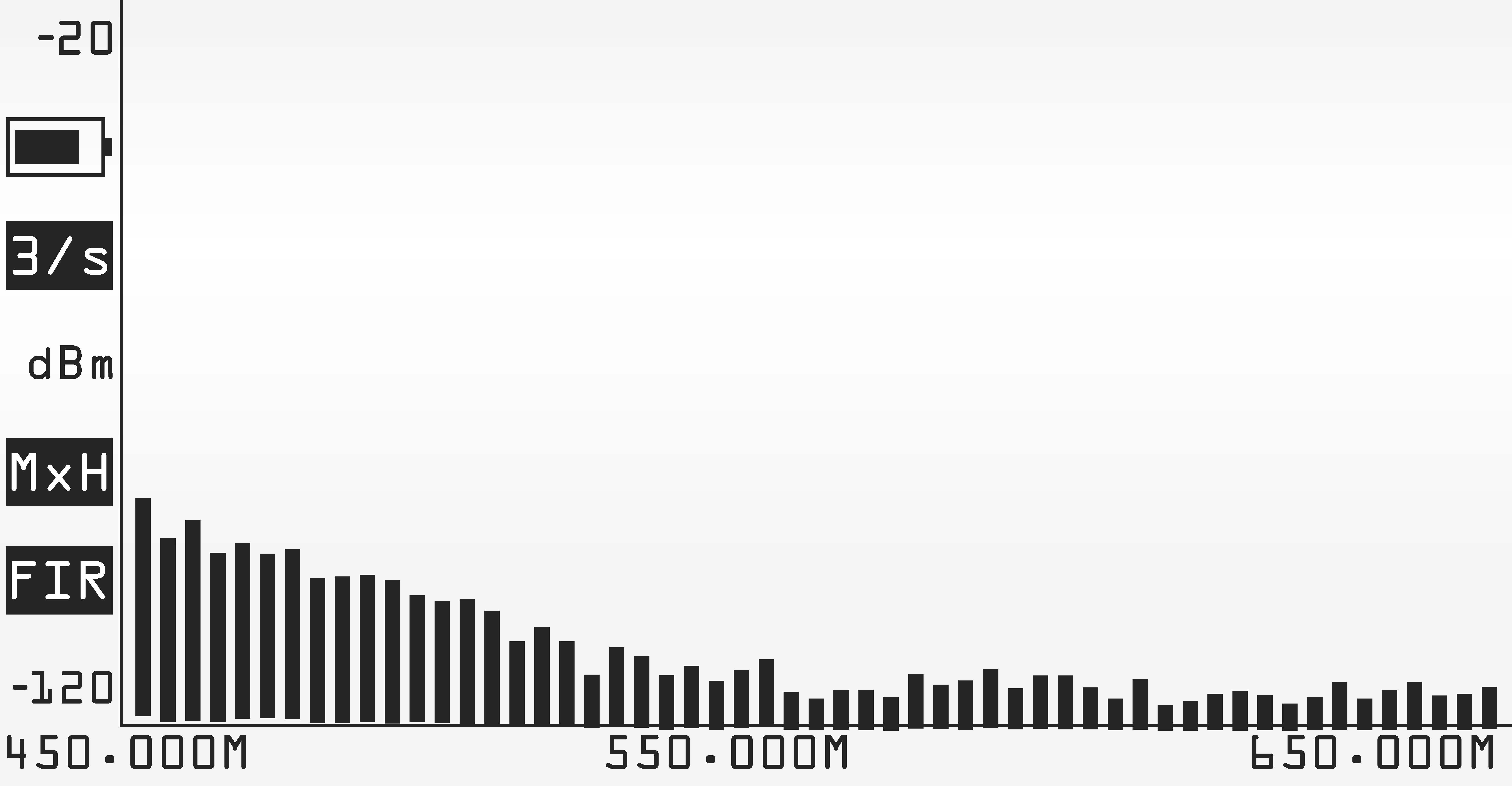
Remember, rogue RF transmissions can come from many sources, not just wireless mics from neighboring venue but video equipment, anything with a motor, or anything that quickly switches current on and off quickly. This kind of interference will typically look like little narrow spikes. If by chance you have assigned a channel directly on top of one of these you will either need to correct the interference at the source or move your mic channel. Checkout our video that demonstrates this effect with an arc welder!
Intermodulation Distortion (IMD)
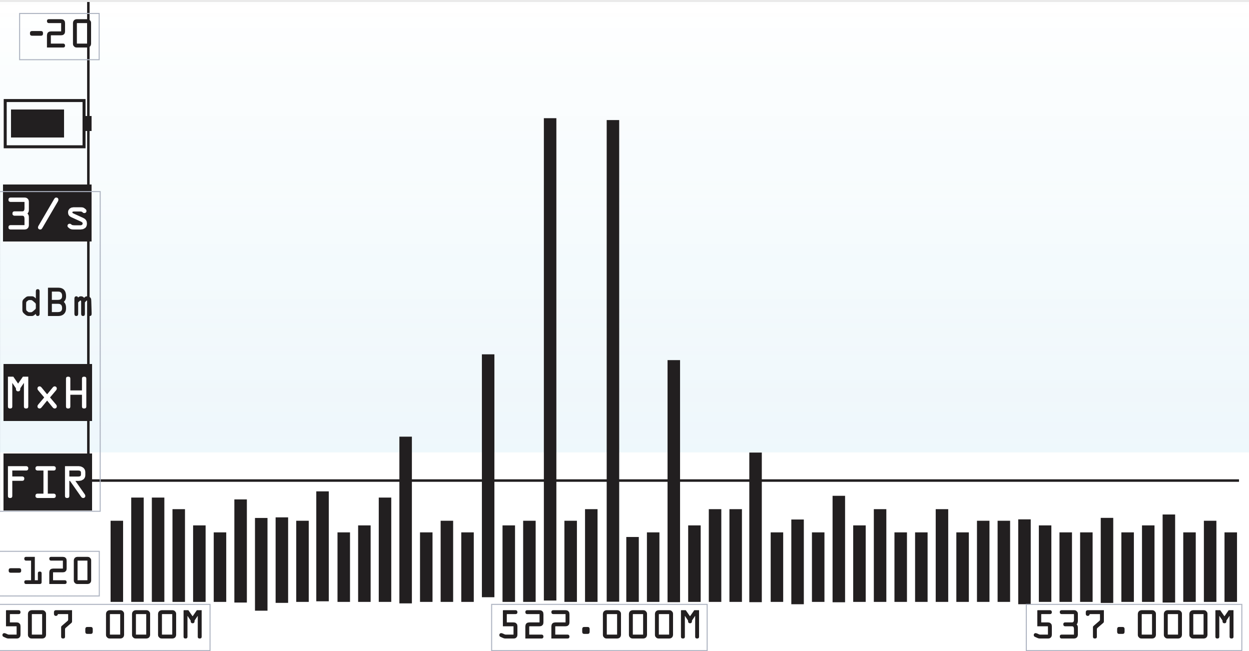
IMD’s signature looks very much like your actual intended signal but hopefully at a much lower level. If you see anything close you will want to set your scan width to be very narrow so that you can see the absolute frequency of a close IMD spike. And if you get one of these little peaks very close to your intended frequency you will need to reassign some channels. Using a frequency coordination program you can be mostly free from this problem, but it is never absolute. Which is exactly why you need to see your RF environment with a spectrum analyzer as sometimes the calculations are not the best they could be. Be aware that even if the IMD frequencies are relatively low, they can grow quickly. In fact for every 1dB your intended signal grows the IMD amplitude grows 3 dB so it can quickly overrun your intended channel frequency.
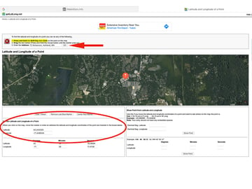
Over-the-Air TV Stations
In the US, over-the-air commercial television broadcasts in solid blocks that are 6MHz wide and easily identifiable. Most EU stations broadcast in an 8MHz block. In a large urban location this screen might look nearly full, in a rural location there maybe just one that your spectrum analyzer can pickup.
How to Manage Interference
The general idea is now that you can see identify interference, you can further identify frequency ranges that are clear. You will no longer have to guess as to the amount of clear open space that you have available in your venue. And please remember, the RF spectrum is dynamic and things do change at any time. Although scheduled to be completed by July 20, 2020 all TV stations have not completely moved to their new assigned frequencies and new repeaters are still coming on line. 600MHz cell phone service is not completely active and new White Space services are coming online.
One key consideration in managing interference is antenna selection and placement. The Spotlight antenna is an excellent option in a high noise floor or crowded RF environment. By localizing reception of the wireless transmitters to one area of use, the Spotlight provides excellent signal to noise for your wireless mic transmitters, and generally minimizes the pick up TV stations, neighboring wireless mic or IEM systems, and other sources out of its range. When paired with bandpass filters, the results can be quite dramatic as shown in the video below:
Reliable operation of wireless mics and IEMs is becoming more challenging every day. The ability to visualize the RF environment and identify interference can be the difference between success and failure. But armed with this detail on the spectrum environment you're operating in, you can take the necessary steps to optimize your system's signal to noise performance and dramatically increase your likelihood of success, even in the most difficult circumstances!