One part was not enough. And another part, “Part Three,” will follow this.
Last week’s post on the futility of wireless gear shootouts received a mixed response, for good reasons.
Some perceived the overall message of the article to be that testing gear—any kind of gear, in any way—is not something that can be accurately performed by an individual end-user, and objected to that perceived message.
Those who left comments raised valid points that gear testing, demos, and shootouts are an important part of the decision making process for building out an audio kit customized to individual needs.
However, audio gear, generally, is not the same as wireless audio gear.
We remain steadfast in our assertion that DIY wireless range tests are so fraught with inaccuracies that they should be abandoned as the only method of determining a wireless device or system’s capabilities (as many professionals often do), or at least taken in stride with specifications and other types of tests, or performed over more than one session.
Gear vs. Wireless Gear
Testing wireless is a greater challenge than testing audio-only gear.
With audio gear—like mixers, amplifiers, recorders/playbacks, DSPs, and to a lesser degree microphones—comparing device to device in an A/B scenario is more reliable, and simpler, because there are fewer unknowns to take into account.
An audio-only device chain (microphone the exception) is comprised of links/devices that are isolated from the outside world. They receive inputs and create outputs of signals, but those signals are your signals, electromagnetically shielded by an enclosure or PCB and carefully shielded by an audio cable, under your control.
When one link in an AF device chain is replaced with another link for the purposes of comparison, the input signal at that link remains exactly the same, so you can be much more certain that differences you hear between devices’ outputs are caused by differences in the devices, rather than something else.
Signal chains that include radios are different. Both transmitters and receivers use antennas. Antennas of any type might be thought of (vaguely, but for the purposes of explanation, let’s roll with it) as a wide open hole in an imaginary roof on the house of an RF system.
Although antennas vary in quality and have much diversity in design, as a whole, the conducting/radiating elements of antennas do not discriminate between radio waves with any logic or intention. Depending on antenna design, waves of higher or lower frequency may be more or less efficiently converted into signal-carrying EM energy fed into a transmission line, or may have greater sensitivity to radio waves in one direction and lesser sensitivity in another, but all antennas convert or conduct radio waves to some degree.
Wireless receivers must select and isolate one signal on one carrier frequency from all other signals and noise the receiving antenna feeds to it. Some receivers are better at this than others, no doubt, but since the antenna connected to that receiver is conducting the entire spectrum of radio waves (albeit many orders of magnitude more efficiently within that antenna’s tuned range, i.e. UHF), and that spectrum from the perspective of the receiver is always changing, even in the absence of anything an operator may or may not do, and changing significantly based on the physical location, frequency, and behavior of a paired transmitter, you can’t be nearly as sure when comparing gear that differences in audio quality or range are due to one receiver or another, or one antenna or another, and nothing else.
The spectrum is a living, changing ecosystem, it gets into your signal chain through the antenna, and most of it is completely out of your control.
Too often, in our experience, we’ll ship off an antenna, usually a Diversity Fin, and someone will do a range test on it against another antenna (sometimes one with higher gain and an amplifier) and return the antenna and say, “it doesn’t work.”
In the case of the Diversity Fin, if range is the only thing you care about, maybe the Diversity Fin is not the correct antenna for your application, but that’s a far cry from the antenna being broken or defective. The Diversity Fin was designed primarily for the elimination of multi-path dropouts in indoor environments, among other benefits, so putting it head to head against an antenna with 19 dB of directional gain with an in-line amplifier is like comparing a miter saw to a woodchipper: they both do useful things well, but are for separate applications.
But all too frequently, range tests are not performed accurately, and/or end-users are comparing apples to oranges.
Lack of control of dynamic variables in the real-world is the biggest challenge to obtaining accurate results from a wireless shootout.
According to Edward Tufte, “we live in a multivariate world,” whose complexity always exceeds our ability to measure and meaningfully display multiple variables in a simple, comprehensible way.
RF is a crazy, crazy thing. It does crazy things that defy both intuition and, occasionally, known laws of physics. It is never in the same place or behaving exactly the same way more than once. The performance of any wireless system must take known variables (antenna gain, Tx power, every single device in the device chain, and component in each device, indoor/outdoor, ambient spectral conditions, etc) into account, while recognizing that knowing everything about the behavior of a wild-caught radio wave is impossible because of the multi-variate world in which they exist.
There is a reason why manufacturers who design quality RF systems and components test the performance of their products in anechoic chambers, in combination with real-world tests.
RF anechoic chambers (distinct from acoustic anechoic chambers) are electrically shielded rooms: rooms that block as close to 100% of external radiation using conductive shielding and dense walls, and are coated on the inside with materials that prevent RF inside the room from bouncing around. In other words, they impose scientific control upon natural environment so measurements can be taken with as little influence from the natural world as possible.
The chambers look like this:
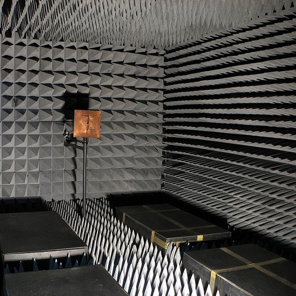
They look… chambered.
And they are very expensive.
Most are custom built by specialist contractors, and priced in the millions of dollars for a full one. Full anechoic chambers are larger to allow more configurations of two or more devices or objects within the chamber, support a wider range of frequencies, are shielded externally, padded internally, and outfitted with passive sensor arrays and computer systems to measure and visualize observed behavior of devices and objects that emit, receive, or interact with radio waves.
Most companies don’t even have an anechoic—we don’t—because they are too expensive to build, calibrate, and operate. Most products are sent off to private laboratories for anechoic testing.
After a rumor spread in 2010 that the antenna on the iPhone 4 was causing dropped calls, Apple revealed the existence of a spectacular RF anechoic hidden somewhere in the depths of California earth which purportedly cost $100 million to build.
Apple chose to reveal the existence of its chamber as a public relations move to quell the rumor. And yes, it was a rumor. There was nothing wrong with the antenna, but rather, possibly (no one but Apple knows for sure) attenuation of signals when the phone was held in a particular way. Or, maybe the dropped calls were network related, or X related, or Y related. Who knows? But they weren’t the result of a botched antenna, in the sense of the electrical design of the antenna; the mistake was in ergonomics and UX not communicating with RF component engineering.
The antenna was an easy target for consumer outrage, because you can’t see or hear RF, and in real-world scenarios you can’t say dropped calls were not caused by the antenna. Even an iPhone user with a degree in RF engineering would not be able to definitively say that dropped calls were caused by a bad antenna when using the phone in the real-world, using off-the-cuff observations.
We don’t have a $100 million anechoic chamber (yet), and I’m pretty sure you don’t have one, either.
It’s tempting to set up a simple, one-time, easy comparison to try and get at the truth of whether one wireless system or component is better than another, but we should all resist that temptation, because we will never arrive close to truth with a single test.
Wireless products often fail to reveal their quality in a brief period of time, because a small period in one location under one set of RF conditions is not enough time to collect data and observe system behavior to arrive at a valid conclusion.
If we want to know how well, for example, an antenna performs, it’s more useful to keep a logbook over a long period of time, and describe interference events with as much context as possible: RF conditions at a site, weather conditions at a site, what RF looks like when the venue is empty and gull, geologic and structural features of a site, nearby interference threats, ALL equipment in use (including cables, connectors, power supplies, and non-RF devices in close proximity to wireless), audible characteristics and durations of interference events, spectrum scans, Tx to Rx distance, IMD calculations, beltpack placement, talent behavior, and what if anything changed to resolve interference.
It’s also a good idea to keep a baggie of clown balloons, because RF behavior can be wacky, unexpected and, to some paid professionals, frightening.
[PART THREE]

Wireless interference graphic courtesy emilegraphics