We often hear these three terms confused or used interchangeably. Although they all begin with the letters POLAR, they are distinct concepts, and confusing one over the other could lead to grave mistakes and/or people pointing and laughing.
Here are three simple explanations and practical take-aways on the three terms.
Polarization
“Polarization” describes the shape of movement an electromagnetic wave takes on as it moves through space. It is the waves themselves that are polarized, but, since sending a wave through an antenna results in polarization, antenna information sheets will usually include “polarization” as a specification, which describes what type of polarization characteristic the antenna will give to the wave, or which polarization they are most efficient at receiving.
Antennas that are linearly polarized are antennas that restrict the movement of the electric EM field to a single direction as it moves through space, which you might think of as flat, like a ribbon. Within linear polarization, there are two subtypes, vertical polarization and horizontal polarization. These two types depend on however the antenna is oriented in relation to the earth. A paddle antenna that is mounted perpendicular to the earth’s surface is said to be vertically polarized, and if parallel, horizontally polarized.
Waves and antennas can also be circularly or elliptically polarized. In both circular and elliptical polarizations, the electric field spins along a fixed axis over time, sort of like twisting the flat ribbon mentioned above. Here is a video that demonstrates polarization. Helical antennas are the most frequently encountered circularly polarized antennas. The Spotlight antenna is elliptically polarized.
Wave polarization is hard to visualize. This video by Youtube user "Ruff" does a great job of illustrating the concept.
Polarization is extremely important to the deployment of wireless audio systems. The energy that leaves a transmit antenna will be more likely to make it through the receive antenna if the receive antenna matches polarizations with the transmit antenna, and, conversely, if the orientation of linear polarization of an incoming wave is directly opposite to the receiving antenna, you can easily get a dropout! In a perfect and static world, transmit and receive antennas would always be identically oriented. But in the world of wireless audio it just doesn’t happen. Performers are always changing the orientation of transmit and receive antennas by moving around with their beltpacks and handhelds, and waves bouncing off walls and other reflective surfaces usually undergo some transformation of polarization, meaning that waves receive antennas try pick up almost never have a consistent polarization.
Circularly polarized antennas like helicals usually provide a performance increase in both transmit and receive applications, because of the element’s ability to more easily match any possible polarization. Polarization diversity antennas like the Diversity Fin are similarly effective at matching polarization, and when used in a diversity receive system are able to completely eliminate multi-path dropouts.
Polar Pattern
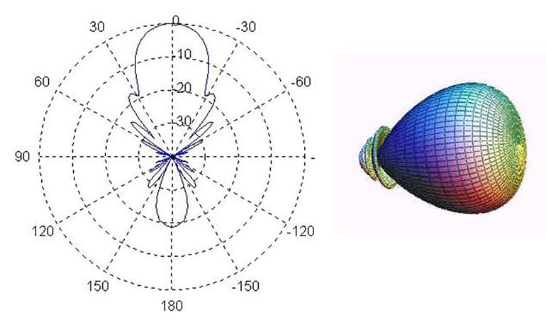
A polar pattern, generally, is a graphical representation of measurements of a transducer's sensitivity or emission strength along degrees of rotation.
In other words, polar patterns are used to show how a transducer responds to or emits fields according to direction, and measures only one two-dimensional plane of space. The most common transducers that use polar plots in our industry are microphones and antennas.
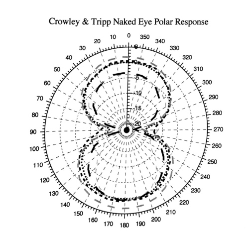
Here’s a polar pattern from a microphone.
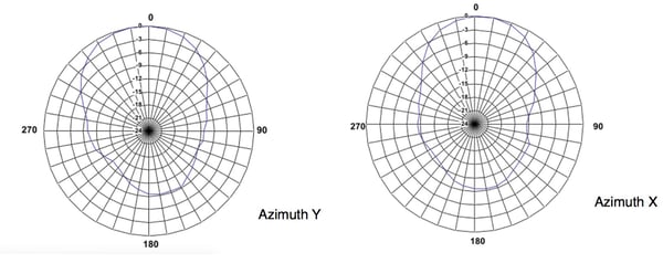
And here are two from the CP Beam antenna.
When we create polar plots for our antennas, for example, we put the antenna to be measured on a special turntable in a special room, and point a reference antenna located a precise distance away at the turntable. We send a wave of constant power through the reference antenna, and then turn the turntable, one degree at a time, measuring how much energy the antenna under test picks up at that point in rotation. Then, we take the data and scale and graph it into a polar plot. Each data point, which contains amplitude and degree, is graphed at the corresponding angle around the center of the graph. Since the antenna is not equally sensitive in all directions, the polar plot shows the amount the antenna varies in sensitivity in different directions.
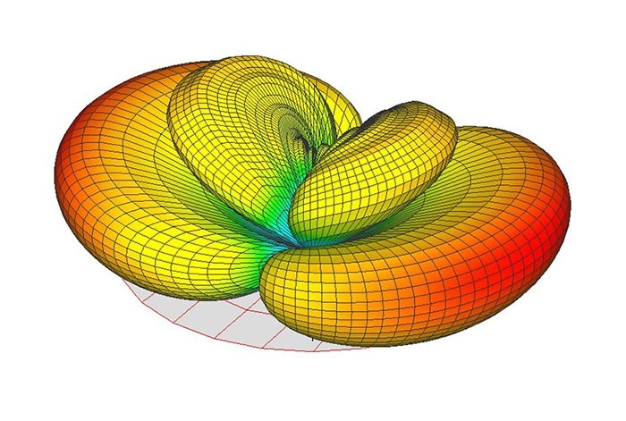 3D plot of radiation pattern. Courtesy "Cwru3."
Now, polar plots are very useful but they are limiting in that one polar plot is only one slice of the field. An antenna radiates along an infinite number of planes, not just one. “Radiation patterns” are three-dimensional representations of antenna patterns, but you need very expensive test and measurement facilities to accurately create them, and/or expensive physics modeling software, which is why you don’t often see radiation patterns as a standard specification, though they would be useful. We sometimes will take polar plots for two perpendicular azimuths to give you a good idea of how the antenna responds horizontally and vertically.
Polarity
Polarity is the direction of current flow in a circuit. That is, within one system, however the movement of electrons move through a conductor from one place to another.
It’s no use getting too technical on this one, because it boils down to semantics, and in fact there are some very deep and quantum mysteries surrounding the movement of electrons, that I have no business lending a botched explanation to. The + and - signs familiar to us are distinguishing between one direction from another, rather than concretely “forward” or “back.” In an A/C system those markings have more to do with matching the alternation pattern of current than marking a strictly one-way electron street as in a D/C circuit.
 Animation of current flow.
Anyways, when it comes to electrical polarity, consult your user manual. And don’t use the word “polarity” to describe antenna polarization. Electrical polarity has nothing to do with antennas and is not the same thing as antenna and electromagnetic wave polarization.