 I think by now everyone is on board that having an antenna farm is NOT a best practice. But what exactly makes them a problem? Let’s take a look.
The Easy Ones
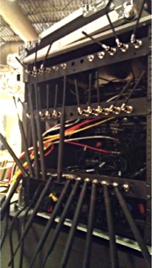
To achieve best diversity performance, your antennas (whips and paddles) should be at precise 90° angles to each other. This is nearly impossible to achieve if you have multiple receivers mounted in a rack. And it goes without saying that if the farm is inside a metal rack you’re headed for a bad day anyway. Another obvious problem is if all the antennas are in the rack there is a lot of potential interference from power supplies and any digital equipment nearby. And lastly, having your antennas down at knee height will nearly always ruin line of sight to the microphones.

Mutual Coupling Losses
Think about radio waves traveling through space. When the signal reaches an antenna, the electrons in the antenna are energized by that EM wave and your antenna absorbs some of the energy from the wave as it passes. The wave is somewhat reduced in power in a similar fashion to how an audience full of water bags (human bodies) soak up a little sound energy. The result is the antennas are stealing a little power from each other.
Increased noise floor
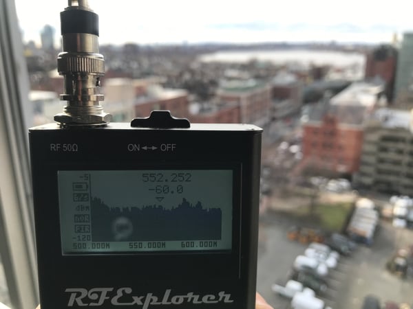
This one is not as obvious. But antennas are receiving and re-broadcasting at the same time. As that radio wave moves up and down the antenna it creates a current. And as that current moves up and down your antenna it creates an EM wave (which come to think about it is how a transformer works). So you likely end up with neighboring antennas that are broadcasting into each other. Likewise as the front end of your receiver converts those currents into something it can demodulate it leaks a bit of signal backwards back out into your antenna where it is broadcast out and into your other antennas in the farm which will show up as an increase in noise floor.
Array Forming
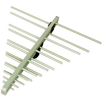
The most common form of antenna is a single wire ... your basic dipole whip. But if you look at the traces on a paddle antenna you see a there are a number of different length traces, carefully designed to interfere with each other and create desired polar patterns. Yagi antennas (pictured above) are an easy to understand example. Bringing that all back to an antenna farm, it’s easy to visualize how a bunch of dipoles in close proximity are going to cause unknown shifts in the polar patterns of each other.
Best Practices
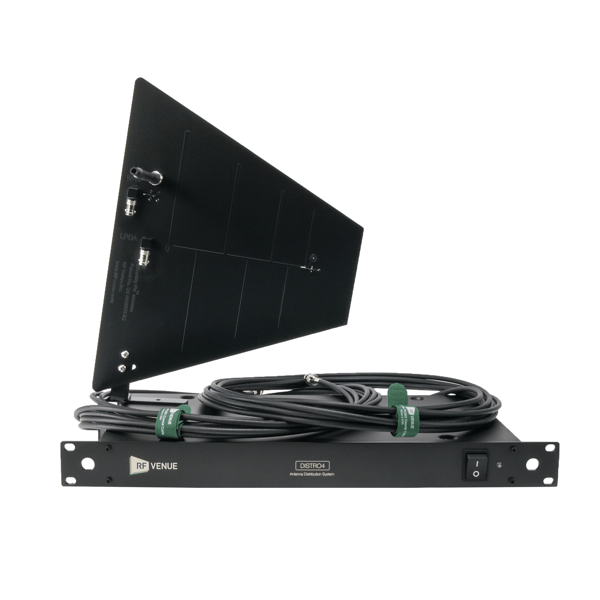
Probably none of these factors by themselves are necessarily a deal-breaker. But in these days of shrinking bandwidth and increased interference, best practices say do yourself a favor and get an antenna distro system with a proper remote antenna setup.