It probably goes without saying that to have successful wireless mic operation, you need to get a good signal from the transmitter, through free space, and then through the receiving antenna, through the coaxial cable, through the distro, and into the receiver.
That’s why it might seem counterintuitive to advise that active antennas — i.e., antennas that have built-in electronic amplification — aren’t always the best answer for that first stage of the receiving side of your wireless mic system.
Typical small-signal RF amplifier circuits, like those used in active antennas, in-line amps, and elsewhere in a receiving-side RF chain, have a limited dynamic range. They are reasonably linear for low signal levels but grow increasingly non-linear for signals that may be of larger-than-expected amplitude. Non-linearity in an RF circuit can be tolerated for a single frequency, a single signal, because the harmonic artifacts produced are fairly low in amplitude and are at frequencies that are 2×, 3×, 4× and higher multiples of the original carrier frequency, and therefore are easy to filter out.
But when multiple signals mix, non-linearity causes intermodulation distortion (IMD) that is potentially more harmful than the simple harmonic distortion that occurs on a single frequency.
IMD raises the noise floor in the slice of UHF spectrum that we use and may crowd the wireless mic frequencies that we want to receive cleanly, without dropouts and distortion. Figure 1 shows nine wireless mic frequencies and the resulting complex RF waveform received by the antenna. The power spectrum is clean, dominated only by the nine carrier signals.
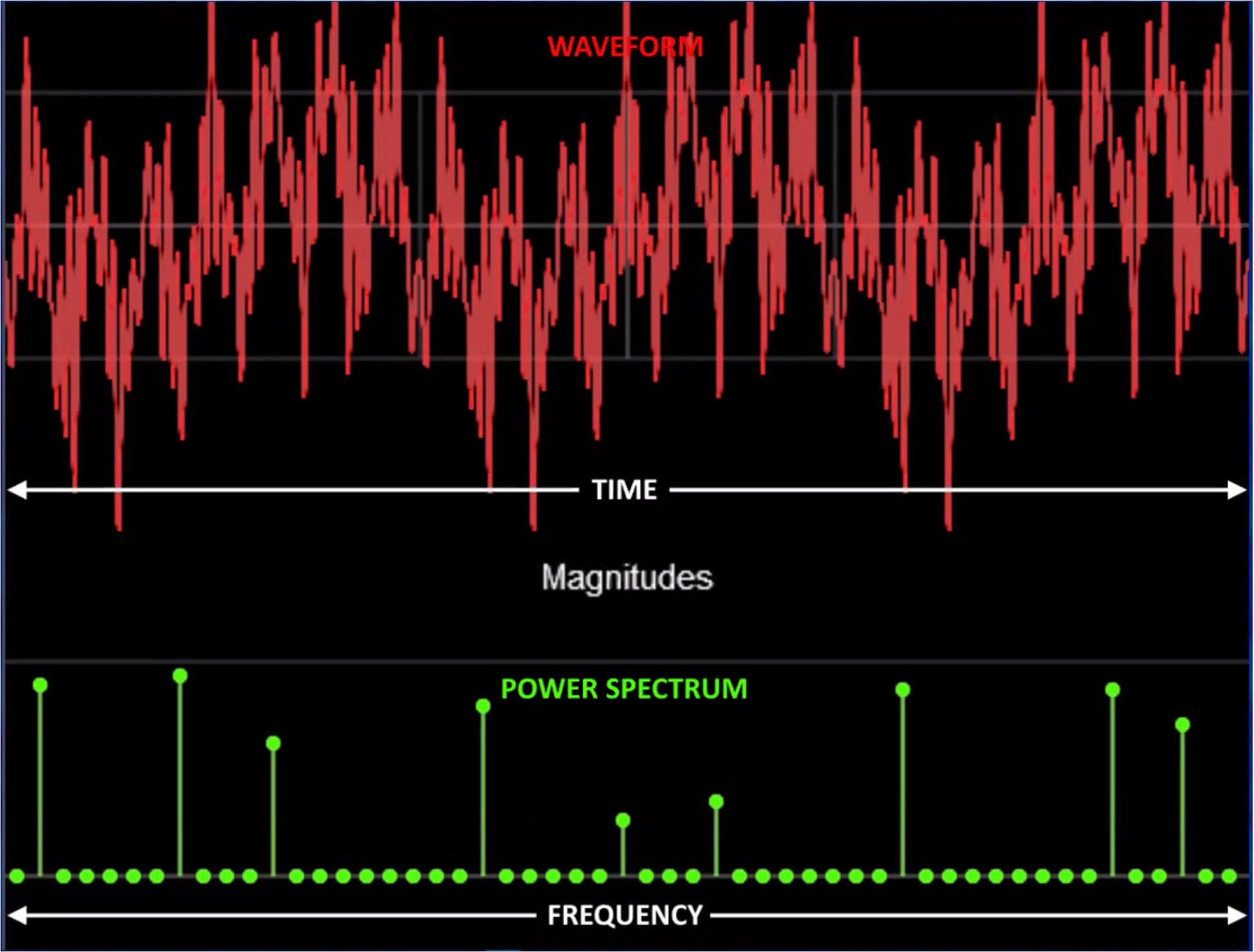
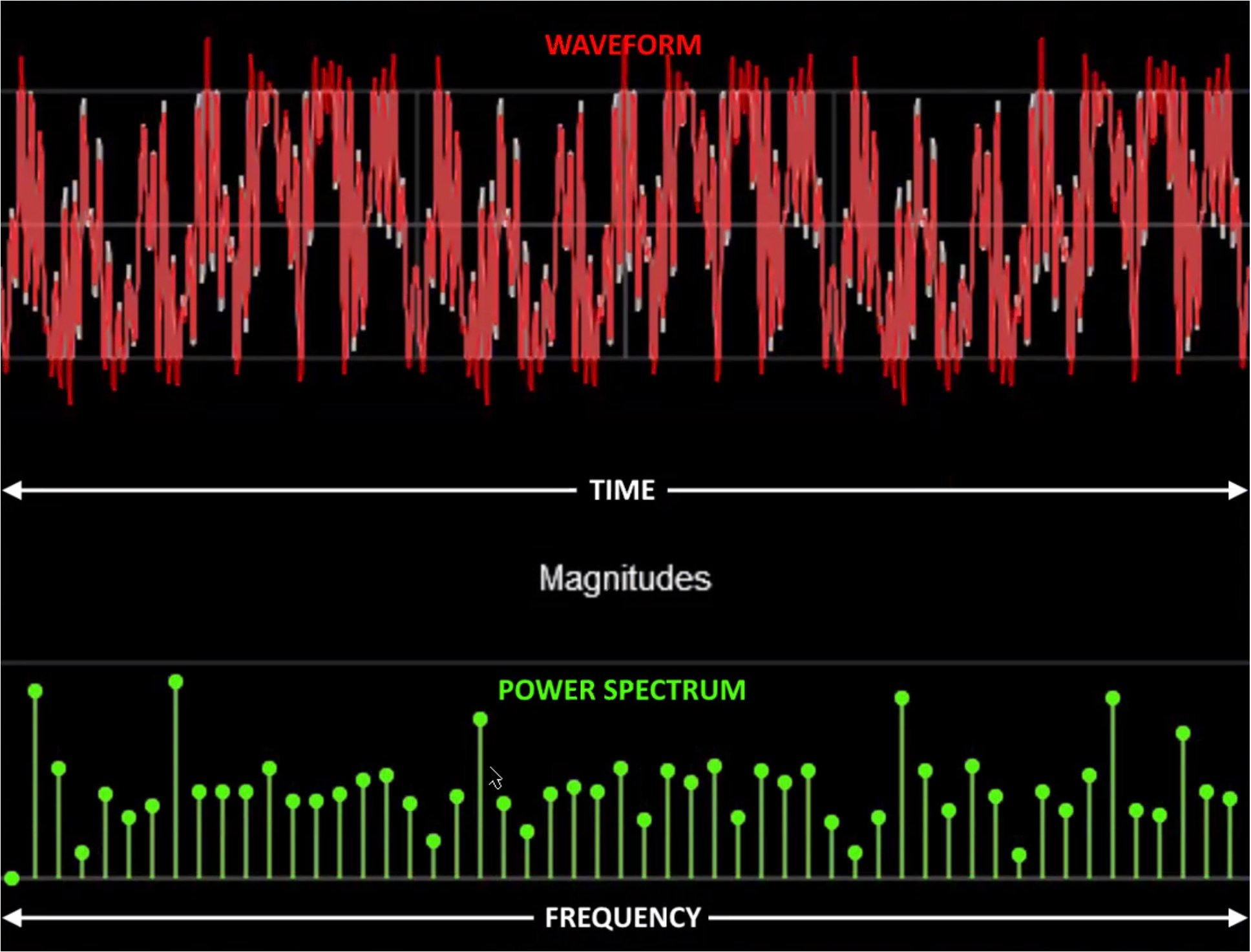
Figure 2 shows what happens when the complex signal of nine combined frequencies overloads an active circuit. The power spectrum becomes dense with intermodulation products, severely raising the noise floor.
Contrary to some myths, intermodulation does not happen in the air, in free space. It’s a phenomenon that only occurs in non-linear circuits. Particularly, active circuits. A good practice for wireless mic reception is to minimize the number of active stages in the RF path as much as possible. Therefore, passive antennas are almost always a better solution than active antennas. If you have the very rare situation where the received signals are extremely weak, you can always add in-line amplifiers only as needed.
A last thought: Passive antennas, unlike active ones, can transmit as well as receive. So passive antennas like the CP Beam or the CP Architectural Antenna in your inventory can be used for IEM use or for wireless mics.
Uh-oh: math, if you want to read further
The artifacts produced by IMD are at the sum and difference of the original frequencies that are mixing. For example, with three frequencies, f1, f2, and f3, these are the resulting IMD products:
f1 + f2 + f3
f1 + f2 – f3
f1 – f2 + f3
-f1 +f2 + f3
The first combination results in a frequency that is well out of our wireless mic band and is easy to filter and ignore. But the other three combinations may produce frequencies that fall on or near enough to the desired frequencies that we want to receive. We call these third-order intermodulation (IM3) products because they develop from three frequency elements.
Complicating this a little further, we also must take harmonic distortion into account and look at the artifacts produced by the second harmonics (the higher harmonic products are small enough to ignore) of the carrier frequencies:
2×f1 – f2
2×f1 – f3
2×f2 – f1
2×f2 – f3
2×f3 – f1
2×f3 – f2
These combinations do not produce IM artifacts that impinge on the original frequencies, but they could do so on a fourth frequency. And that frequency would necessarily be part of additional combinations to calculate. The total number of potential IM combinations grows exponentially with increasing numbers of wireless channels in use. In addition, the possible frequency deviation of the IM products is the sum of the deviations of the original frequencies; if our wireless mics (which use frequency modulation, or FM) can modulate up to ±40 kHz, then IM3 products can potential deviate up to ±120 kHz, and fifth-order (IM5), ±200 kHz.
IM3, and to a lesser extent, IM5 products, are the artifacts that are most likely to compete with the desired signals’ frequencies and thus possibly cause our wireless mic receivers to lose capture effect, where the receiver locks onto the desired signal and demodulates it cleanly. Wireless mic frequency coordination programs such as Wireless System Builder and the Frequency Coordination function in the RF Venue RF Explorer Pro perform these simple arithmetic calculations of all the possible three-frequency (and if selected, five-frequency) combinations. The arithmetic is simple, but the number of calculations becomes overwhelming; it’s best left to computers.