- Products
- All Products
- RF PA Extension Kit
- Wireless Microphone Upgrade Packs
- In-Ear Monitor Upgrade Packs
- Wireless Microphone Antennas
- Wireless In-Ear Monitor Antennas
- Antenna Distribution for Microphones
- Antenna Combiners for In-Ear Monitors
- Multi-Zone Antenna Combiners
- Spectrum Tools
- Accessories, Cables and Parts
- Solutions by Venue
- Resources & Training
- Performance Tools
- About Us
Wireless Audio Essentials
Confident Wireless in
Confident Wireless in
Any Environment.
We design and build specialized antennas and distribution to make wireless mics and IEMs work and sound better. That’s all we do. Wireless can be challenging. So we focus on plug and play products that give you confidence your wireless systems will work every time - with no wireless expertise needed!
RF Venue Products
RF essentials to improve your existing wireless systems.
Meet the Wireless PA Game-Changer
ROAD TEST RESULTS ARE IN
ProSoundWeb’s latest Road Test reveals how the RF PA Extension Kit keeps audio solid across large venues, outdoor events, and worship spaces—no long cables, no headaches

Unlock Wireless Audio Expertise
Struggling with wireless microphone dropouts, poor antenna placement, or RF interference? Our eBooks are packed with expert advice on optimizing wireless audio systems for clearer, more reliable performance. Whether you're managing a live sound rig, a house of worship, or a broadcast setup, our guides will help you reduce signal issues and improve your RF reliability. So, if you're new to RF or a seasoned pro, these resources are packed with practical tips to help you get the most out of your gear.
Download our recent eBooks below, and be sure to explore our full selection to take your wireless system to the next level.

Antennas and Antenna Placement for Wireless Audio, Explained and Demystified
Novice wireless users tend to either underthink or overthink — even agonize over — their antenna decisions. If you operate or are responsible for a wireless audio system — wireless mics, in-ear monitors (IEMs), or both — you need to understand some core antenna concepts
Download eBook
Cracking the Code: Conquering Wireless Drop Outs
This guide unveils the reasons behind frustrating signal dropouts with wireless microphones and in-ear monitors (IEMs). Most importantly, this guide equips you with practical solutions for clear, confident wireless in your venue.
Download eBook
Three Essential Concepts in Wireless Audio
Remove the mystery of RF and helps you better operate your wireless system. You've heard of 'signal to noise' - now you'll know why it's so important to understand with your wireless systems.
Download eBookMake Sure Your Wireless System's Ready
Book a FREE! 30-minute sound system check with an RF Venue expert. We'll review your setup, flag potential issues, and help you hit the busy season with confidence- no pressure, no pitch
Start with RF Venue Performance Tools
Check your performance or build your system with our free tools.
Solutions by Venue
RF Venue makes products to increase reliability for any venue.
RF Venue by the Numbers
Trusted
35
k
+
Installations and implementations of RF Venue products
Confidence
218
k
+
Channels deployed
Availability
75
+
Countries served by RF Venue distributors and dealers
Flexibility
100
%
Brands we work with
Why RF Venue
With over 35,000 installations, RF Venue builds wireless essentials - that’s all we do.
-
Confidence in Your Performance
Unmatched Reliability
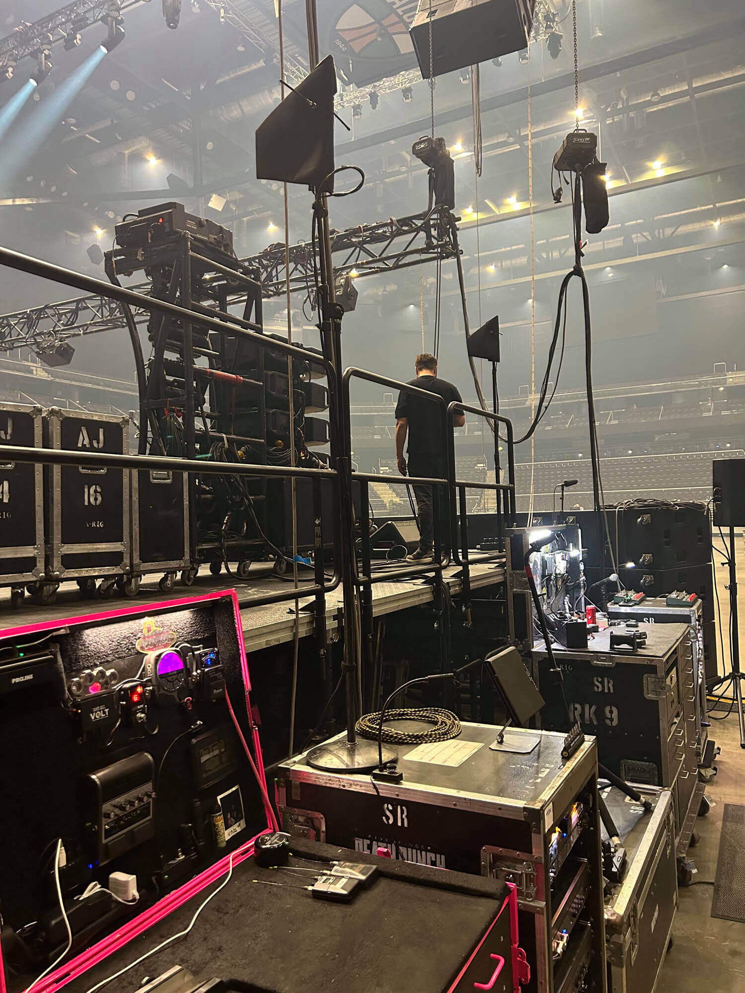
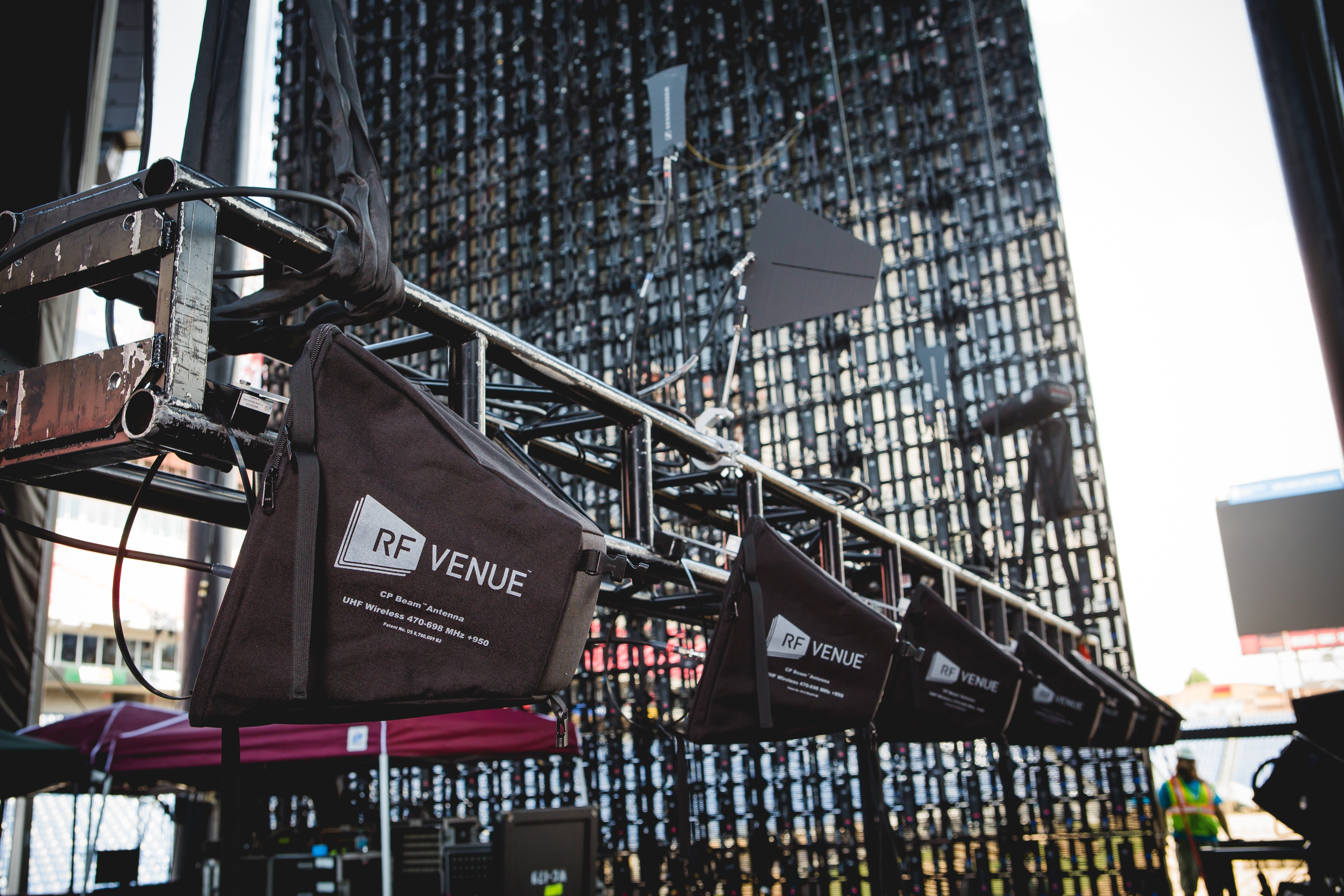
We prioritize providing our clients with unparalleled confidence in their wireless audio systems. Our solutions are engineered to minimize the risk of dropouts and interruptions that can disrupt critical events. Whether you’re an end user, installer, or audience member, our products instill peace of mind, knowing that your wireless audio will continue to deliver in any environment.
-
Expertise & Dedicated Support
Know How & Approachability
Our team of experts brings a blend of technical proficiency and caring dedication to every project, ensuring that our clients feel supported and empowered. Whether you’re a sound designer, technical engineer, project manager, or small business owner, we’re invested in your success and committed to providing the guidance and tools you need to excel in your audio endeavors.
-
Cost-Effective Products and Installation Costs
Get it right the first time
We focus on products that cost less and work better. Our products are easier to install and work the first time. Most importantly, when installing a complex wireless microphone and in-ear monitor system, our customers want to be sure they get it right the first time - which is why our customers continue to work with RF Venue (again and again).
Unmatched Reliability
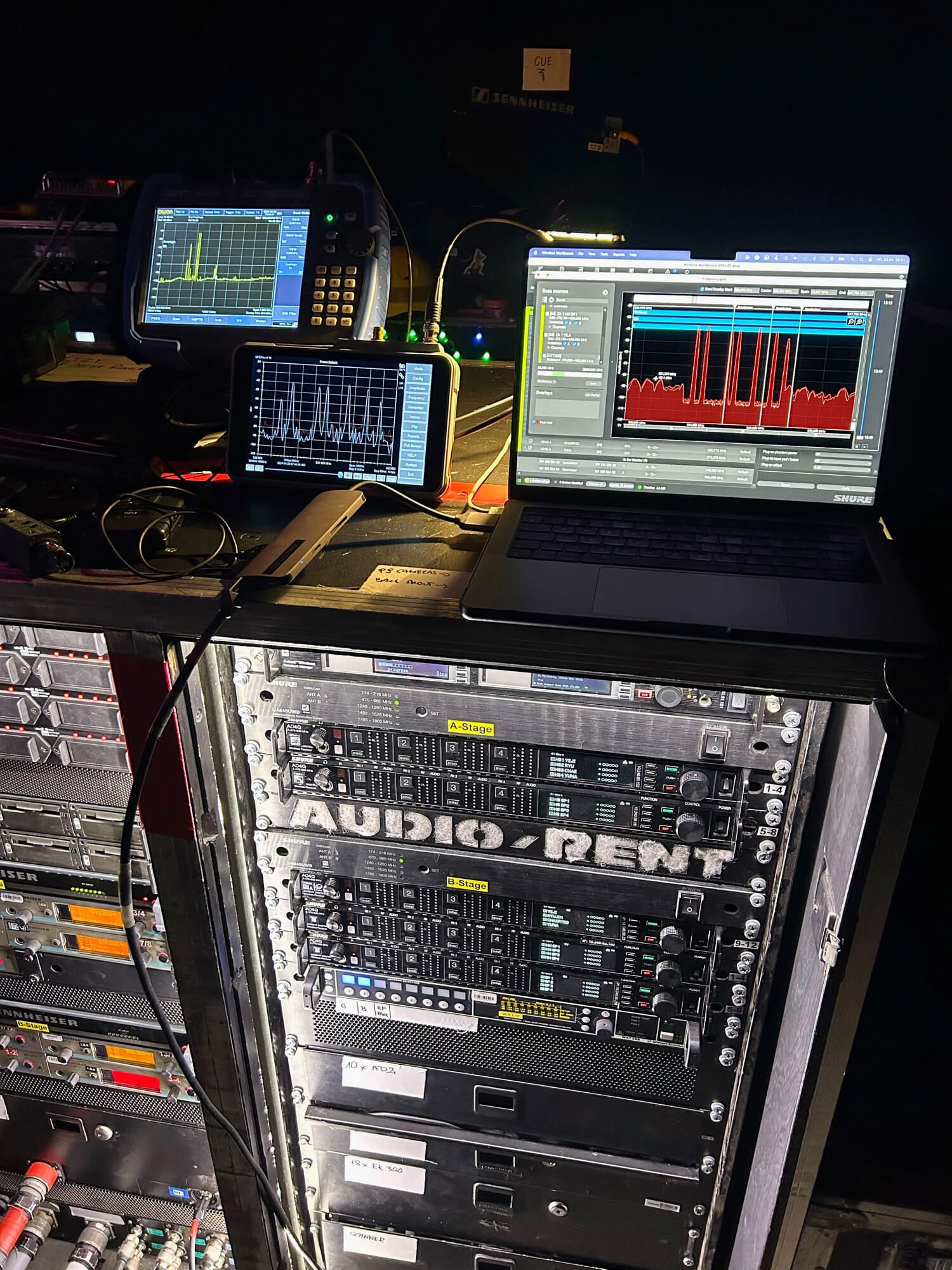
We prioritize providing our clients with unparalleled confidence in their wireless audio systems. Our solutions are engineered to minimize the risk of dropouts and interruptions that can disrupt critical events. Whether you’re an end user, installer, or audience member, our products instill peace of mind, knowing that your wireless audio will continue to deliver in any environment.

Know How & Approachability
Our team of experts brings a blend of technical proficiency and caring dedication to every project, ensuring that our clients feel supported and empowered. Whether you’re a sound designer, technical engineer, project manager, or small business owner, we’re invested in your success and committed to providing the guidance and tools you need to excel in your audio endeavors.

Get it right the first time
We focus on products that cost less and work better. Our products are easier to install and work the first time. Most importantly, when installing a complex wireless microphone and in-ear monitor system, our customers want to be sure they get it right the first time - which is why our customers continue to work with RF Venue (again and again).

“At Porche’ Advanced Systems, LLC, we trust RF Venue for every wireless job because their products deliver exceptional reliability and performance. By using RF Venue, we help ensure frustration-free operation for our clients, minimizing potential interference and signal issues. Their innovative technology and consistent results make them our go-to choice for seamless wireless audio solutions”
Jason Ryder, Porche Advanced Systems
“The team at RF Venue has a massive wealth of knowledge when it comes to RF design and application. Being able to interface with and learn from them on a one hour training was better than any previous RF based training that I have received. It is well worth the time investment for any engineer or field engineer to better understand what they are doing and also the consequences of doing things one way vs another.”
Brandon Meyers, CCS New England
“We love the quality of RF Venue and the ease of installation. We mainly use the RF Venue wireless antenna and distribution for wireless mics and IEMs. We’ve had zero issues thus far with the products we’ve used. Definitely a go to on our projects.”
Greg Klimetz, Relevant AV Solutions
“Every install your products are in have been working great. I've been using the CP Stage a lot lately and it's been great, especially for corporate events where the event people want to see as little of tech as they can”
Chad Griswold, Mastermind Production Group Inc.
“No other system available provides the latitude of solutions RF Venue offers. Keep developing smart products like you do, deliver them cost effectively like you do today, and fix the issues that come up in grand style like you do”
Don Peterson, AVnew LLC
“The very knowledgeable team at RF Venue are extremely dedicated to providing quick technical support. It's rare to find manufacturers that are this dedicated to backing up their customers and providing training whenever requested. ”
Colin Quek, Loud Technologies Asia
Register for our Upcoming Webinars
The Latest From Our Blog

Press Release
RF Venue launches 4 ZONE-Network: remote control added to multi-zone antenna combiner
7 min read
| February 10, 2026
Read More

RF PA Extension Kit
Connecting a PA system wirelessly: Save time, money, materials, and headaches!
8 min read
| December 8, 2025
Read More

Worship AV
Is Your Church’s Wireless System Ready for the Holidays?
13 min read
| December 3, 2025
Read More
Work with RF Venue
RF Venue users already work with all the gear that you use. You should work with us too.


.jpg?length=720&name=cpb%20copy%20(1).jpg)
